175
F3SG-SR
User’s Manual
Chapter4 Basic Operation of SD Manager 3
Setting with SD Manager 3
E
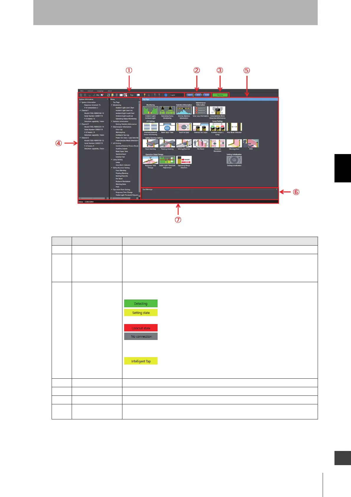
4-2-3-2. Description on Top Page and Each Button
This section hereafter describes each function taking the top page displayed when F3SG-SR is
connected as an example.
No. Function Description
1 Tool Menu The menu can be selected using the buttons.
2 Target sensor Select a target sensor segment to write information to or read information from. The view
changes according to actual cascade connection of the F3SG-SR. The example above
shows the F3SG-SR system with three sensor segments in cascade connection is
connected to the PC.
3 Operating state Shows the operating state of the F3SG-SR or the connecting state of the Intelligent Tap.
F3SG-SR operating states
Operating: The F3SG-SR keeps normal operation.
Setting state: It is possible to read configuration from the F3SG-SR. The
safety outputs of the F3SG-SR are in the OFF state.
Lockout state: The F3SG-SR is in the LOCKOUT State.
No connection: The SD Manager 3 is running offline or disconnected from
or not properly connected to the F3SG-SR.
Intelligent Tap connecting state
Only Intelligent Tap connected: Only the Intelligent Tap is connected with
SD Manager 3. You can check or change the configuration data in the
Intelligent Tap in this state.
4 System Information Shows information on the F3SG-SR connected.
5 Settings Configurable or other functions are displayed.
6 View message Shows messages according to operations and settings of SD Manager 3.
7 Communication
setting indicator
The communication setting of the connected F3SG-SR is displayed.

 Loading...


