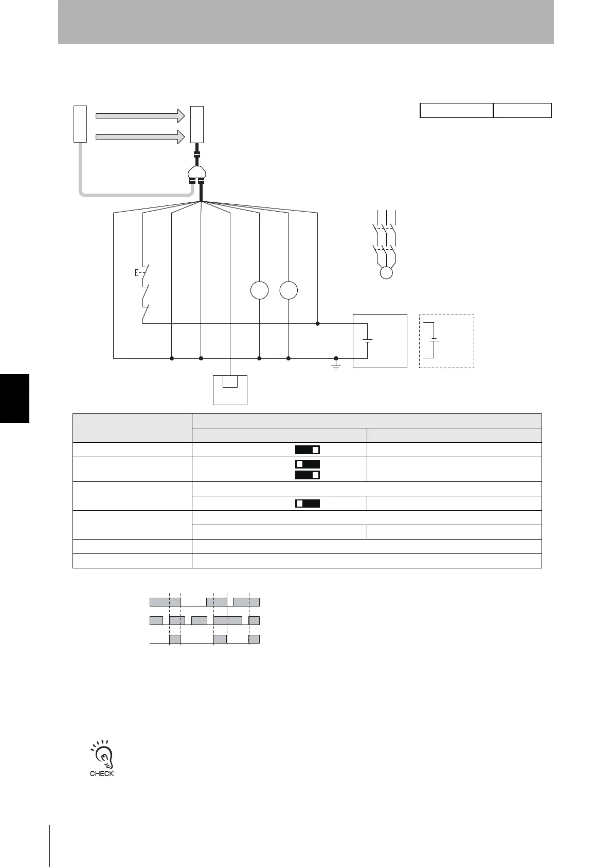
6-2-1-5. Manual Reset Mode with EDM and Y-Joint Plug/Socket Connector
F39-JGR3K-L and F39-JG□B-L
F39-GCNY2
F39-JG
A-D
24 VDC
Wiring for NPN *1
*3
24 VDC
Timing chart
F39-JGR3K-D and F39-JG□B-D
IN
PLC *2
KM1
KM2
M
KM1
KM2
S1
KM1 KM2
Beam state: Unblocked
Blocked
Reset switch (S)
OSSD
S1: Lockout/interlock reset switch
KM1, KM2: Safety relay with forcibly guided contacts (G7SA) or magnetic contactor
M: Motor
PLC: Programmable logic controller (Used for monitoring only. NOT related to
safety system.)
OSSD 1 (Black)
OSSD 2 (White)
24V/0V (Brown)
0V/24V (Blue)
AUX (Red)
MUTE B (Pink)
MUTE A (Gray)
RESET/EDM
(Yellow)
Receiver
Emitter
*1. Reverse the polarity of the power supply when using in the NPN system. Select a
PLC of PNP or NPN type according to the system of your application.
*2. When connecting to the PLC, the output mode must be changed with the SD
Manager 3 according to your application. Refer to Chapter 4 Setting with SD
Manager 3 for more information on setting this function by the SD Manager 3.
*3 This is the case for a PELV circuit.
*4 Set the function with the DIP Switches on the Intelligent Tap or the SD Manager
3, restore the settings to the F3SG-SR, and perform wiring according to the
wiring diagram.
*5 To set the Short mode, set the function with the DIP Switches on the Intelligent
Tap or the SD Manager 3, restore the settings to the F3SG-SR, and perform
wiring according to the wiring diagram.
: Indicates a switch position.
Function
Setting
DIP switch SD Manager 3
EDM *4 EDM Enabled
[Externaldevicemonitoring]:Enable
Interlock *4 Manual Reset [Start interlock] : Enable
[Restart interlock] : Enable
Operating Range Selection *5 Long (factory default setting)
Long [Operating Range Selection] : Long mode
Non-Muting system Perform wiring according to the wiring diagram.
N/A [Muting] : Disable *4
External Test not used N/A
Optical Synchronization Connect the wires according to the diagram above.

 Loading...


