49
F3SG-SR
User’s Manual
Chapter2 Pre-Reset
System Operation and Functions
E
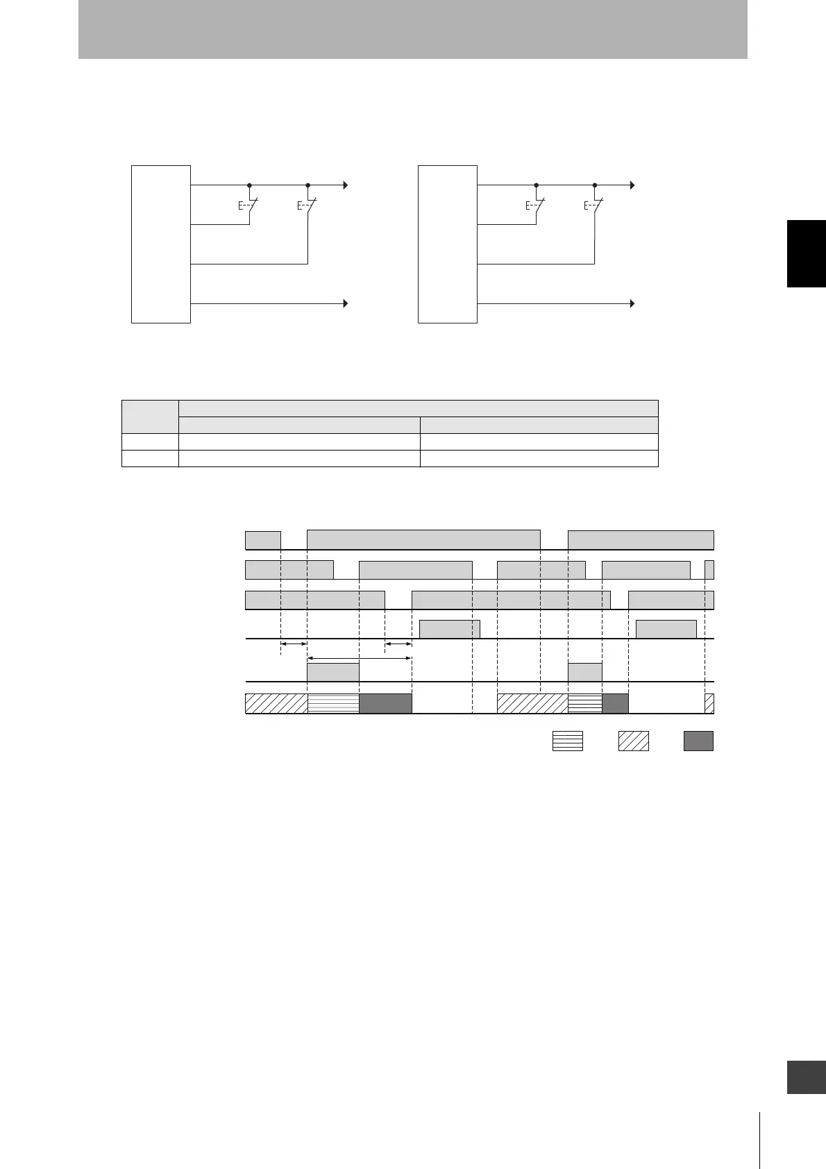
Basic wiring diagram
• Pre-Reset mode
The table below shows the relation between the ON/OFF states and external lines.
Timing chart
This is an example of the maximum number of times the F3SG-SR can be blocked is set at 1.
2-9-2. Factory Default Setting
The Pre-Reset function has been set to disabled.
Input
External connection
PNP NPN
ON Vs-3 V to Vs 0 to 3 V
OFF 0V to 1/2 Vs, or open 1/2 Vs to Vs, or open
+24 VDC
0V
PNP
S1
S2: Lockout or interlock reset switch
S2
0V
+24 VDC
NPN
S1
S2
S1: Pre-reset switch
24V/0V (Brown)
PRE-RESET (Gray)
RESET/EDM (Yellow)
0V/24V (Blue)
F3SG-SR
receiver
24V/0V (Brown)
PRE-RESET (Gray)
RESET/EDM (Yellow)
0V/24V (Blue)
F3SG-SR
receiver
Pre-reset switch
Beam state
Reset switch
OSSD
SEQ indicator
(yellow)
Unblocked
Blocked
*When Auxiliary Output is set to Pre-reset Information by the SD Manager 3.
AUX*
Unexpected beam
block
ON
OFF
ON
OFF
ON
OFF
ON
OFF
ON
OFF
ON 1
time
ON 2
times
Solid-
ON
T1 or longer
T3 or longer
T2 or less
T1: Minimum pressing time of pre-reset switch. Configurable from
100 to 500 ms in 100-ms increments. T3 = T1
T2: Maximum permissible time from input of PRE-RESET signal to
input of RESET signal. Configurable from 8 to 60 s in 1-s
increments.
T3: Minimum pressing time of reset switch. Configurable from 100 to
500 ms in 100-ms increments.

 Loading...


