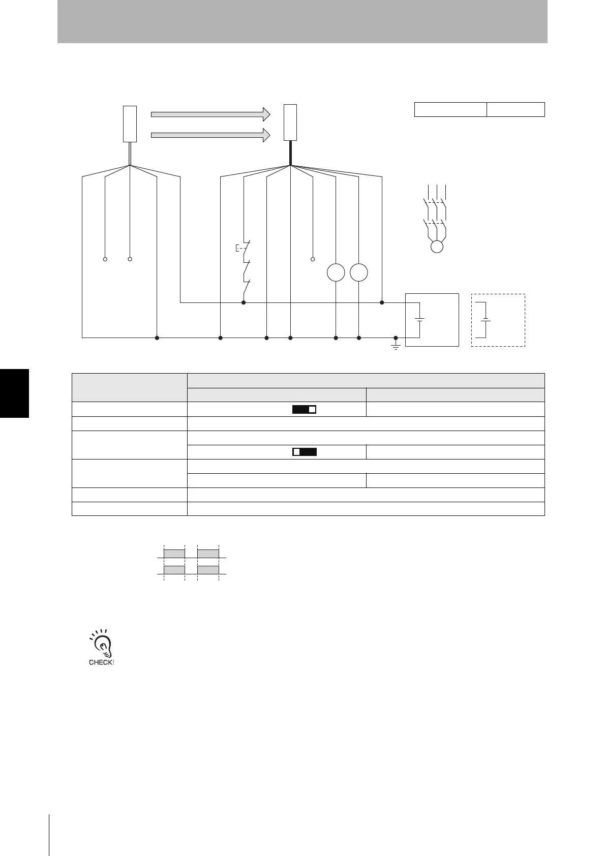
6-2-1-3. Auto Reset Mode with Optical Synchronization and EDM Used
*1. Reverse the polarity of the power supply when using in the NPN system.
*2. Connect the line to 0 VDC if Operating Range Selection is used in Short Mode.
*3. Refer to 2-6. External Test for more information if External Test is used.
*4. This is the case for a PELV circuit.
*5. Set the function with the DIP Switches on the Intelligent Tap or the SD Manager
3,
restore the settings to the F3SG-SR, and perform wiring according to the wiring
diagram.
: Indicates a switch position.
Function
Setting
DIP switch SD Manager 3
EDM *5 EDM Enabled [External device monitoring] : Enable
Interlock Auto Reset (factory default setting)
Operating Range Selection *5
Long : Open the OPERATING RANGE SELECT INPUT line of the emitter or connect the line to 24 VDC.
Long [Operating Range Selection] : Long mode
Non-Muting system Perform wiring according to the wiring diagram.
N/A [Muting] : Disable
External Test not used Connect the TEST line of the emitter to 0V/24V of the emitter.
Optical Synchronization Do not connect the COM(+) and COM(-) lines of the of emitter and receiver with each other.

 Loading...


