EasyManuals Logo

Omron F3SG-SRB Series User Manual

Omron F3SG-SRB Series
399 pages
To Next Page IconTo Next Page
To Previous Page IconTo Previous Page
Page #357 background imageLoading...
Page #357 background image
329
F3SG-SR
User’s Manual
Chapter6 Wiring Examples (for F3SG-SR)
Input/Output Circuit and Applications
E
6-2-2-3. Standard Muting Mode/Exit-Only Muting Mode with Intelligent Tap
[Wiring Example]
• When using the Intelligent Tap (F39-SGIT-IL3), the following functions are not available.
- External Test
- Operating Range Selection by wiring
- Optical Synchronization
• When a functional earth is necessary, wire an earth cable according to the example in 6-2-1-1. Auto Reset Mode with
Optical Synchronization and EDM Unused. Also refer to 5-4-4. Functional Earth Connection for more information.
MUTE A
MUTE B
OSSD
Timing chart
Beam state: Unblocked
Blocked
S1
S2 S3
*3
*8
F39-SGIT-IL3
24 VDC
Wiring for NPN *1
24 VDC
IO-Link
Master *7
F39-JGB-L/
XS5F-D521-DJ0-IL
F39-JG
A-D
F39-JGR3K-L and F39-JGB-L F39-JGR3K-D and
F39-JGB-D
IN
PLC *4
IN1
Safety controller
*5 *6
IN2
Receiver
Emitter
OSSD 1 (Black)
OSSD 2 (White)
24V/0V (Brown)
0V/24V (Blue)
AUX (Red)
MUTE B (Pink)
MUTE A (Gray)
RESET/EDM
(Yellow) *2
*1. Reverse the polarity of the power supply when using in the NPN system. Select a
PLC and a safety controller of PNP or NPN type according to the system of your
application.
*2. Also used as OVERRIDE INPUT line.
*3. Make sure to connect an override cancel switch to the RESET line when using the
override function. Otherwise the override state may not be released by the override
cancel switch, resulting in serious injury.
*4. When connecting to the PLC, the output mode must be changed with the SD
Manager 3 according to your application. Refer to Chapter 4 Setting with SD
Manager 3 for more information on setting this function by the SD Manager 3.
*5. Refer to 6-3. Connectable Safety Control Units for more information.
*6. The safety controller and the F3SG-SR must share the power supply or be connected
to the common terminal of the power supply.
*7. For connecting with the IO-Link Master unit, refer to an instruction manual of the
IO-Link Master unit you use.
*8. This is the case for a PELV circuit.
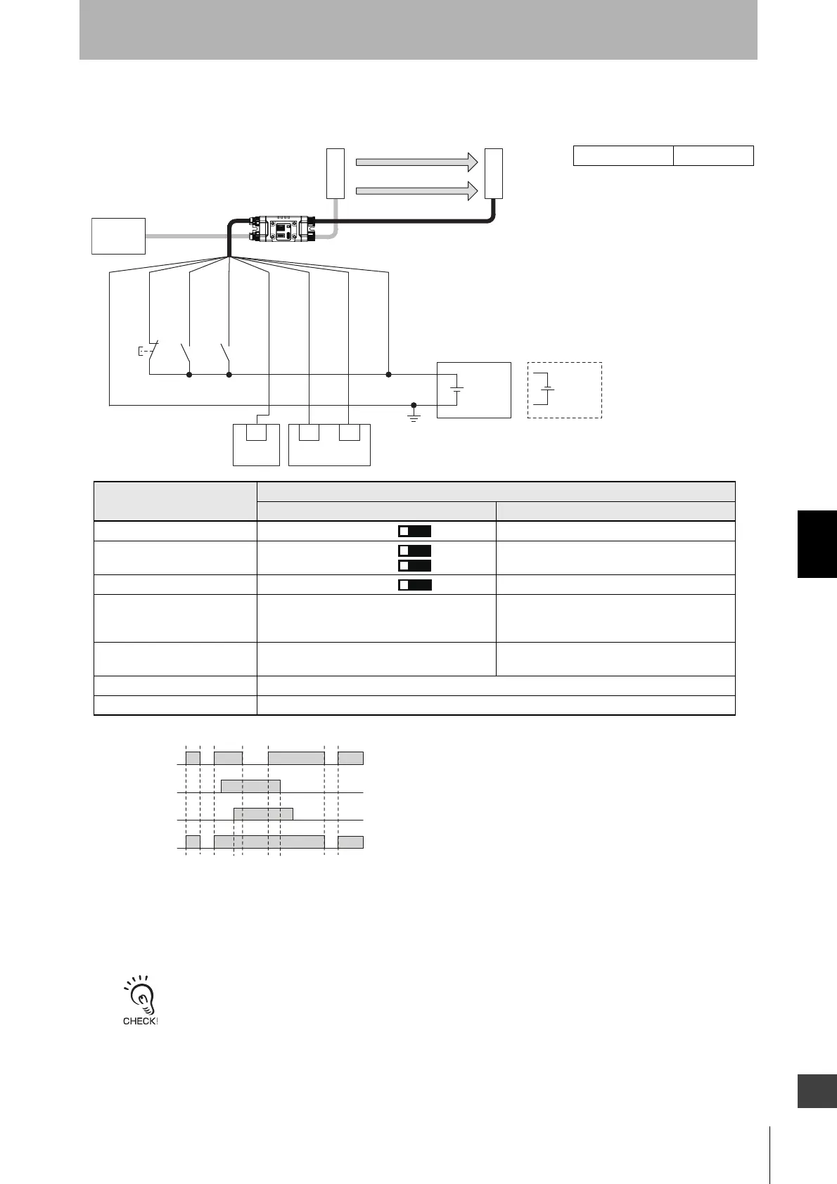
: Indicates a switch position
Function
Setting
DIP switch SD Manager 3
EDM EDM Disabled [External device monitoring] : Disable
Interlock Auto Reset [Start interlock] : Disable
[Restart interlock] : Disable
Operating Range Selection Long [Operating Range Selection] : Long mode
Standard Muting Mode N/A [Muting] : Enable
[Muting mode] : Standard Muting (Installation
Example1/2)
Exit-Only Muting Mode N/A [Muting] : Enable
[Muting mode] : Exit-Only Muting
Test Input N/A
Wired Synchronization Connect the emitter and receiver with the Intelligent Tap.
㻟㻻
㻠㻻
㻡㻻
㻤㻻
S1: Lockout reset switch, override switch or override cancel switch
S2, S3: Muting sensor
PLC:
Programmable logic controller (Used for monitoring only. NOT related to safety system.)
Intelligent Tap Needed

Table of Contents

Questions and Answers:

Question and Answer IconNeed help?

Do you have a question about the Omron F3SG-SRB Series and is the answer not in the manual?

Omron F3SG-SRB Series Specifications

General IconGeneral
BrandOmron
ModelF3SG-SRB Series
CategorySecurity Sensors
LanguageEnglish

Related product manuals