95
F3SG-SR
User’s Manual
Chapter2 Fixed Blanking
System Operation and Functions
E
2-15-3. Setting with Intelligent Tap
Fixed blanking can be configured using Positions 6 and 7 of the DIP Switch of the Intelligent Tap.
The Fixed Blanking Monitoring function is configured as Lockout.
Make sure the Position 2 of the DIP Switch is set at ON (DIP Switch Enabled) to activate the settings by the DIP Switch.
Refer to Chapter 3 Setting with Intelligent Tap for more information on setting this function by the Intelligent Tap.
2-15-4. Setting with SD Manager 3
The user can make changes to the settings of this function by the SD Manager 3.
Setting is required for each sensor segment in case of a cascade connection.
It is recommended that the Position 2 of the DIP Switch be set at OFF (DIP Switch Disabled).
Setting the Fixed Blanking Monitoring function to Disable Monitoring may create an undetectable area where a person
can block the F3SG-SR without being detected, and it is not compliant with IEC 61496-2. Conduct risk assessment
analysis thoroughly before enabling this setting.
Refer to Chapter 4 Setting with SD Manager 3 for more information on setting this function by the SD Manager 3.
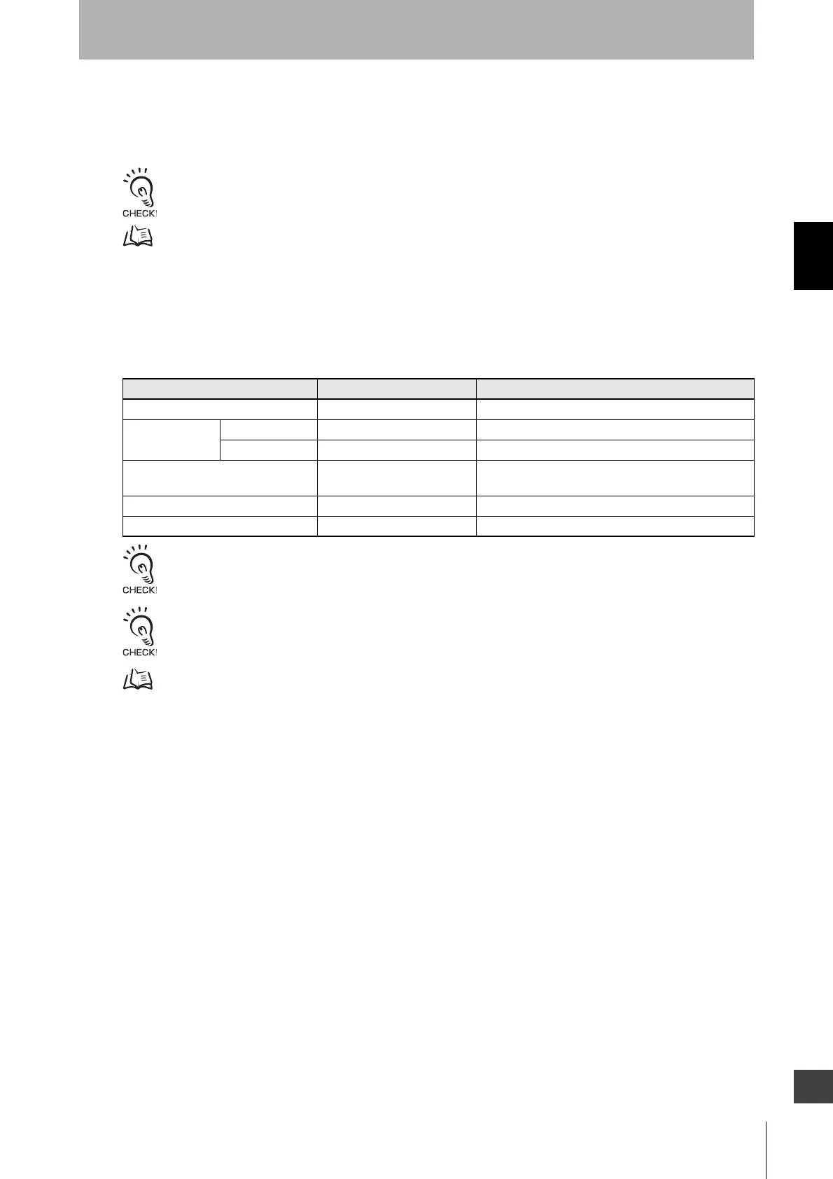
Function Initial value Configurable value or numerical range
Fixed Blanking Disable Enable/Disable
Fixed Blanking
zone
Bottom beam 1 any beam in 1-beam increments
Top beam 1 any beam in 1-beam increments
Fixed Blanking Monitoring Lockout Lockout/Disable monitoring/Cancel blanking zone/
Quick blanking
Number of allowable upper beams 0 beam 0 to 5 beams in 1-beam increments
Number of allowable lower beams 0 beam 0 to 5 beams (1-beam increments)

 Loading...


