324
Chapter6 Wiring Examples (for F3SG-SR)
F3SG-SR
User’s Manual
Input/Output Circuit and Applications
6-2-1-9. Pre-Reset Mode with Reset Switch Connector
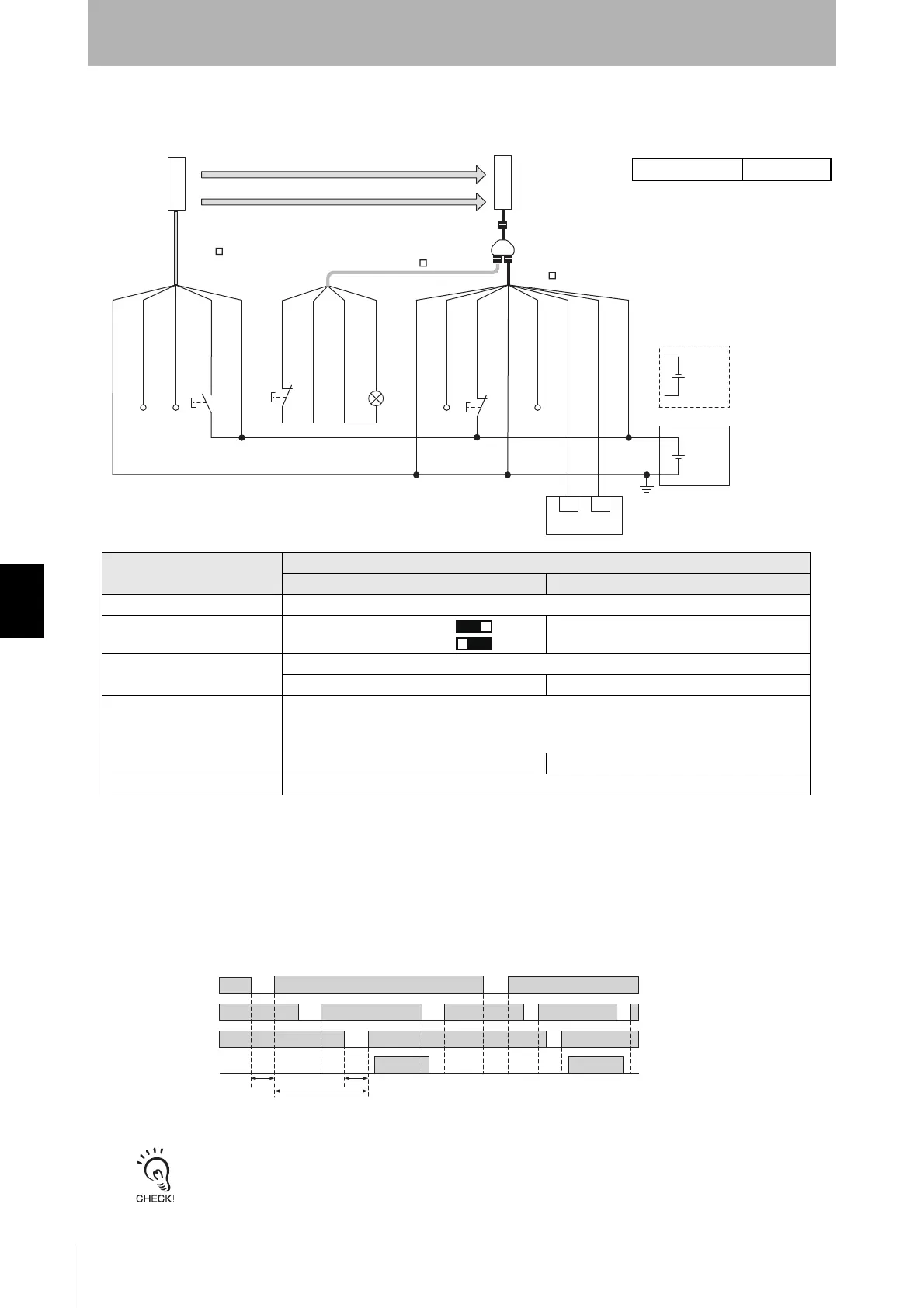
[Wiring Example]
• When using the Reset Switch Connector (F39-GCNY3), the following functions are not available.
- External Device Monitoring (EDM)
•
When a functional earth is necessary, wire an earth cable according to the example in 6-2-1-1. Auto Reset Mode with
Optical Synchronization and EDM Unused. Also refer to 5-4-4. Functional Earth Connection for more information.
S2
S1
24 VDC
24 VDC
F39-JG C-L
F39-GCNY3
F39-JGR3K-D
XS5F-D421 80-F
F39-JG
A-D
IN1
IN2
L1
Wiring for NPN *1
OSSD 1 (Black)
OSSD 2 (White)
24V/0V (Brown)
TEST (Black)
Not used (White)
24V/0V (Brown)
0V/24V (Blue)
0V/24V (Blue)
AUX (Red)
Not used (Pink)
PRE-RESET (Gray)
RESET (Yellow)
0V/24V (Blue)
RESET (White)
24V/0V (Brown)
AUX (Black)
OPERATING
RANGE SELECT
INPUT (Yellow) *2
Emitter
Receiver
Safety controller
*3 *4
*5
S3
Intelligent Tap Needed
S1: Test switch
S2: Lockout/interlock reset switch
S3: Pre-reset switch
L1: Lamp
: Indicates a switch position
Function
Setting
DIP switch SD Manager 3
EDM N/A
Pre-Reset *6 Pre-Reset [Pre-Reset] : Enable *6
Non-Muting system Perform wiring according to the wiring diagram.
N/A [Muting] : Disable *6
Operating Range Selection Long : Open the OPERATING RANGE SELECT INPUT line of the emitter or connect the line to
24 VDC.
External Test used Connect the TEST line of the emitter to 24V/0V via a test switch (NO contact). *7
N/A [External test signal inversion] : Disable
Optical Synchronization Do not connect the COM(+) and COM(-) lines of the of emitter and receiver with each other.
Timing chart
Pre-reset switch (S3)
Reset switch (S2)
OSSD
T1 T3
T2
Beam state: Unblocked
Blocked
Unexpected beam
block
T1: Minimum pressing time of pre-reset switch. Configurable from 100 to 500 ms in 100-ms increments.
T2: Maximum permissible time from input of PRE-RESET signal to input of RESET signal. Configurable from 1 to 60 s in 1-s increments.
T3: Minimum pressing time of reset switch. Configurable from 100 to 500 ms in 100-ms increments.
*1. Reverse the polarity of the power supply when using in the NPN system. Select a safety controller of
PNP or NPN type according to the system of your application.
*2. Connect the line to 0 VDC if Operating Range Selection is used in Short Mode.
*3. Refer to 6-3. Connectable Safety Control Units for more information.
*4. The safety controller and the F3SG-SR must share the power supply or be connected to the common
terminal of the power supply.
*5. This is the case for a PELV circuit.
*6. Set the function with the DIP Switches on the Intelligent Tap or the SD Manager 3, restore the settings
to the F3SG-SR, and perform wiring according to the wiring diagram.
*7. This is the example for the PNP system to stop emission when the line is connected to 24 VDC and for
the NPN to stop emission when the line is connected to 0 VDC. If TEST switch is not needed, refer to
2-6. External Test.

 Loading...