315
F3SG-SR
User’s Manual
Chapter6 Input/Output Circuit
Input/Output Circuit and Applications
E
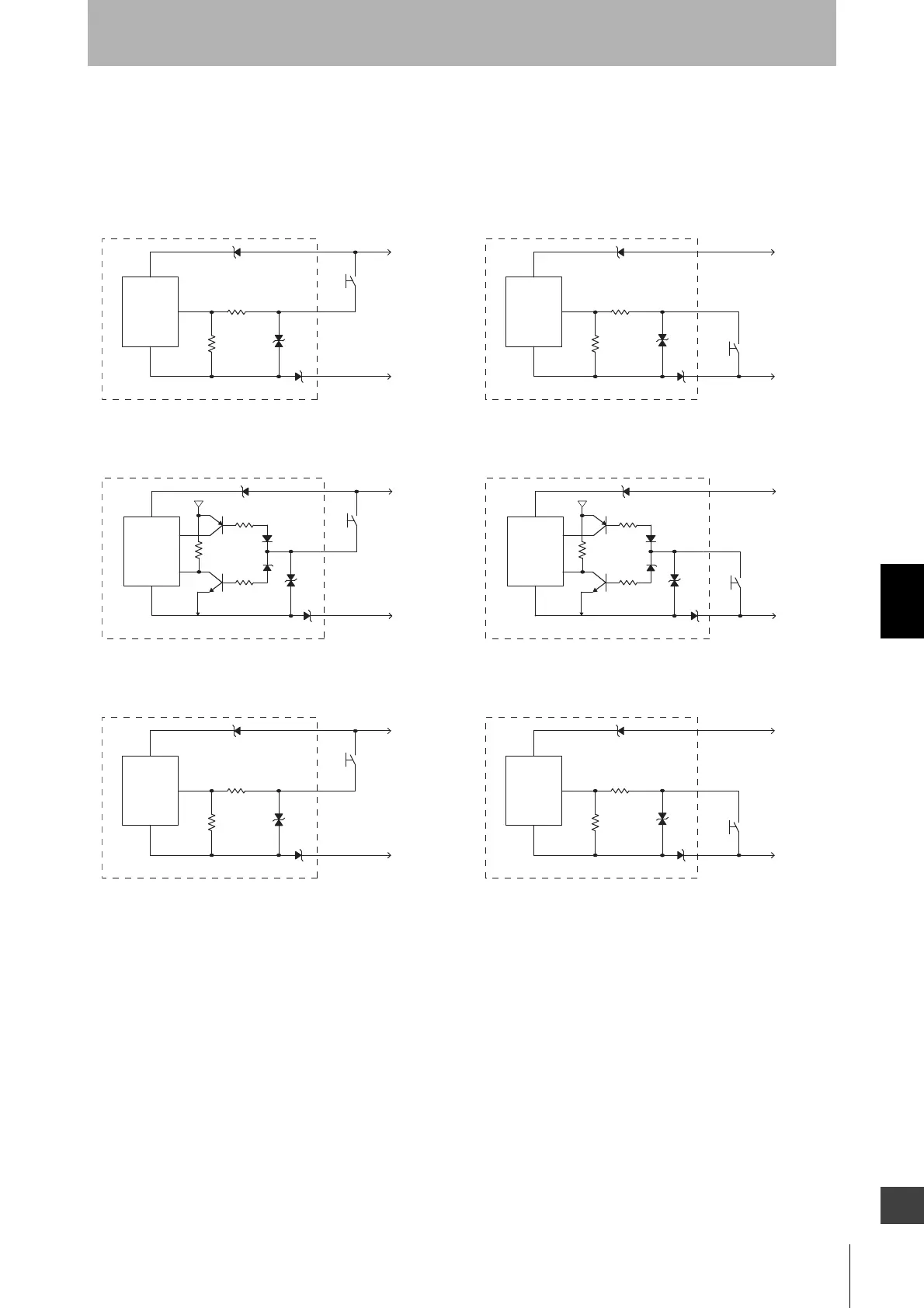
6-1-2. Input Circuit Diagram by Function
The input circuit diagrams of by function are shown below.
Test Input
Test Input, Operating Range Select Input
RESET/EDM, MUTE A/B
Emitter
main
circuit
+24 VDC
0 VDC
Short circuit
current
Approx. 6.0 mA
<Light emission stops when connected to 0 V><Light emission stops when connected to 24 VDC>
Emitter
main
circuit
+24 VDC
0 VDC
Short circuit current
Approx. 5.0 mA
<Short>
Emitter
main
circuit
+24 VDC
0 VDC
5 V
Short circuit
current
Approx. 4.2 mA
<Long>
+24 VDC
0 VDC
5 V
Short circuit
current
Approx. 4.2 mA
Emitter
main
circuit
Receiver
main
circuit
+24 VDC
0 VDC
Short circuit
current *2
<NPN><PNP>
Receiver
main
circuit
+24 VDC
0 VDC
Short circuit
current *1
*1. Short circuit current: approx. 9.5 mA (RESET/EDM),
approx. 4.5 mA (MUTE A/B)
*2. Short circuit current: approx. 13.0 mA (RESET/EDM),
approx. 7.0 mA (MUTE A/B)

 Loading...


