7
F3SG-SR
User’s Manual
Chapter1 List of Key Features
Overview and Specifications
E
1-3-2. List of Key Features
The F3SG-SR has the following features. Some of the features are available or configurable by the
Intelligent Tap (F39-SGIT-IL3) or the SD Manager 3 (PC configuration tool). Sensor status monitoring
is available by the SD Manager 3 Mobile APP, which is the configuration tool for smartphones or
tablets.
*1. DIP Switch is on the F39-SGIT-IL3 Intelligent Tap.
*2. The F39-SGIT-IL3 Intelligent Tap is necessary to use the SD Manager 3 or SD Manager 3 Mobile APP.
*3. Mutual interference can be prevented by Optical Synchronization or Wired Synchronization.
*4. Mutual interference can be prevented by Scan Code Selection.
*5. In the case of setting by DIP Switch or SD Manager 3. For the setting by wiring, it is selectable from the Long and Short modes.
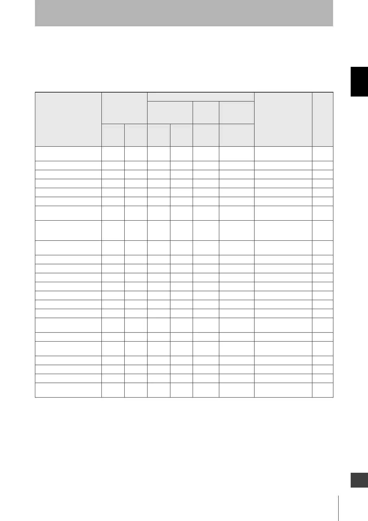
Feature
Availability
Setting/Monitoring by
Factory default setting Page
Sensor
Intelligent
Tap
PC /
Smartphone /
Tablet
F3SG-
SRA
F3SG-
SRB
Wiring
End
Cap
DIP
Switch
(*1)
SD Manager 3
SD Manager 3
Mobile APP (*2)
Mutual Interference
Prevention
XXX *3X *4- -
Code A *4
p.35
PNP/NPN Selection X X X - - - - p.39
External Test X X X - - - - p.42
Interlock X X - - X X Auto Reset p.45
Pre-Reset X X - - X X Disabled p.48
PSDI X X - - - X Disabled p.51
External Device Monitoring
(EDM)
XX - - X X
Disabled
p.54
Auxiliary Output
XX - - - X
Safety output
information (Inverted
signal output: Enabled)
p.57
Muting
XX - - - X
Enabled
(Standard Muting)
p.61
Override X X - - - X Enabled p.85
Fixed Blanking X X - - X X Disabled p.90
Floating Blanking X X - - X X Disabled p.96
Reduced Resolution X X - - - X Disabled p.101
Warning Zone X X - - - X Disabled p.104
Operating Range Selection X X X - X X Long *5 p.110
Response Time Adjustment X X - - - X Normal p.112
Area Beam Indicator (ABI)
X--- - X
Block/Unblock
information
p.113
Designated Beam Output X X - - - X Disabled p.116
Stable Light Threshold
Adjustment
XX - - - X
170%
p.118
Light Level Monitoring X X - - - X - p.119
Maintenance Information X X - - - X - p.120
Operating Status Monitoring X X - - - X - p.123
Instantaneous Block
Detection Information
X--- - X
Enabled
p.124

 Loading...


