194
Chapter4 Changing Settings with SD Manager 3
F3SG-SR
User’s Manual
Setting with SD Manager 3
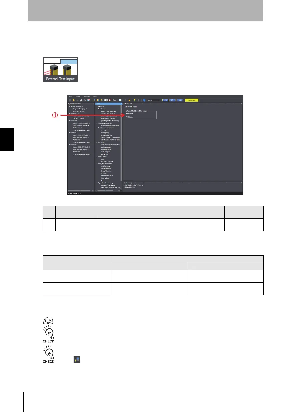
4-3-2-4. External Test Input
First, carry out 4-3-1. Preparing to Change Settings.
Next, on the Top page, click the icon below.
The setting screen below is displayed.
By setting either enable or disable of the external test signal inversion to PNP/NPN selection, the
condition to stop emission can be selected. Refer to the table below.
*1. This can be set using SD Manager 3.
*2. This can be set by wiring.
For more information on external test signal inversion, refer to 2-6. External Test.
When changing the settings is complete, confirm the settings and write the configuration to the F3SG-SR.
To enable the written configuration, refer to 4-2-7-3. Writing Configuration into Intelligent Tap.
When connecting the Intelligent Tap to a F3SG-SR and trying to return the F3SG-SR to [Detecting], follow step 4 of
4-1-3-2. Connection Procedure When Using USB Connector to restart the F3SG-SR and Intelligent Tap, or click the
[Monitor] button.
No. Function name Description
Initial
value
Configurable value
or numerical range
1 External Test Signal
Inversion
Set either enable or disable of the external test signal
inversion.
Disable Enable/Disable
External Test Signal Inversion *1
Input voltage
PNP setting *2 NPN setting *2
Disable (factory default setting)
Emission stops by connecting with 24 V
connection.
Emission stops by connecting with 0 V
connection.
Enable
Emission stops by connecting with 0 V
connection.
Emission stops by connecting with 24 V
connection.

 Loading...


