258
Chapter5 Installation Considerations
F3SG-SR
User’s Manual
Wiring and Installation
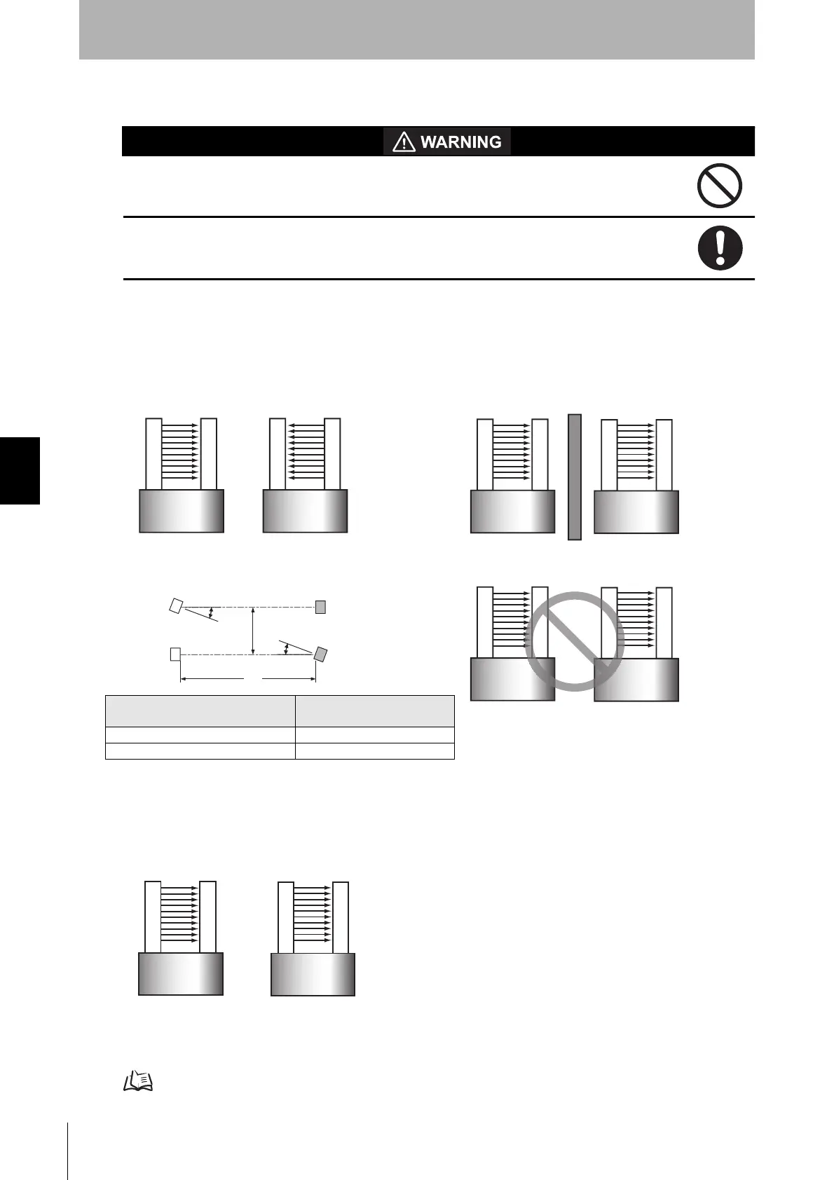
5-1-4. Mutual Interference Prevention
Do not use the F3SG-SR with mirrors in a retro-reflective configuration. Doing so may
hinder detection. It is possible to use mirrors to alter the detection zone to a 90-degree
angle.
When using more than one set of F3SG-SR's in adjacent areas, the emitter of one F3SG-
SR may interfere with the receiver of the other, causing the safety functions to stop working
properly. Install, configure and maintain them so that mutual interference does not occur.
When two or more F3SG-SR systems are mounted in close proximity to each other, precautions
should be taken to avoid one system interfering with another, such as by beam alignment, back-to-
back configuration, physical barrier, Scan Code Selection, Operating Range Selection or adjusting the
distances from adjacent safety light curtains.
Example
In the Wired Synchronization, mutual interference is prevented in up to 3 sets, using interference light
avoidance algorithm.
In the Optical Synchronization, the scan code feature allows for placement of up to 2 sets of the F3SG-
SR in close proximity and in line with each other. The distinctive coding of the beams provide for
unique operation of a system while in view of another system with a different scan code. Two unique
codes are available.
The emitter and receiver units must be set to the same scan code for the receiver to enter the
MACHINE RUN state. The scan code is selectable by the End Caps on the emitter and receiver units.
Refer to Scan Code Selection under 2-3-1-1. Optical Synchronization for more information on the scan code feature.
Emitter
Receiver
Machine 1
Emitter
Receiver
Machine 2
PREFERRED INSTALLATION 1
Code A Code A
Emitter
Receiver
Machine 2Machine 1
Emitter
Receiver
PREFERRED INSTALLATION 2
Code A Code A
Emitter
Receiver
Machine 2Machine 1
Emitter
Receiver
NOT RECOMMENDED INSTALLATION
Code A
Code A
Back-to-back configuration Physical barrier between systems
PREFERRED INSTALLATION 3
Emitter
Receiver
Emitter
Receiver
Code A
Code A
Code A
Code A
L
D
5°
5°
Distance between emitter and
receiver (operating range L)
Allowable installation distance
D
For 0.2 to 3m 0.26m
For 3m or more L x tan5 ° = L x 0.088 (m)
Machine 1
Emitter
Emitter
Receiver
Machine 2
Receiver
Code A
Code B
Scan code setting when two or more systems are mounted

 Loading...


