325
F3SG-SR
User’s Manual
Chapter6 Wiring Examples (for F3SG-SR)
Input/Output Circuit and Applications
E
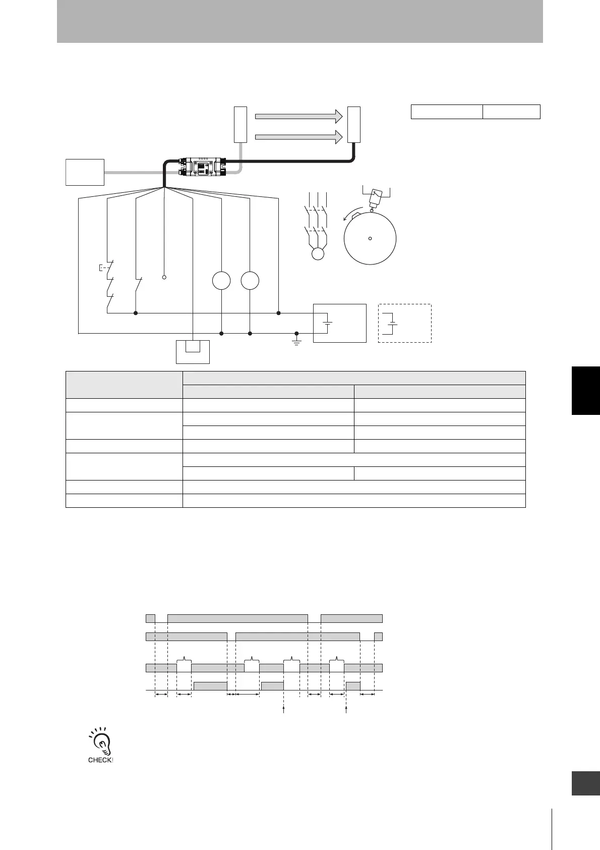
6-2-1-10. Single Break with EDM and Intelligent Tap
[Wiring Example]
• When using the Intelligent Tap (F39-SGIT-IL3) with the emitter and receiver connected, the following functions are not available.
- External Test
- Operating Range Selection by wiring
- Optical Synchronization
•
When a functional earth is necessary, wire an earth cable according to the example in 6-2-1-1. Auto Reset Mode with
Optical Synchronization and EDM Unused. Also refer to 5-4-4. Functional Earth Connection for more information.
S1
KM1 S2
KM2
F39-SGIT
24 VDC
IO-Link
Master *3
Wiring for NPN *1
24 VDC
F39-JG□B-L/
XS5F-D521-DJ0-IL
F39-JG
A-D
F39-JGR3K-L F39-JGR3K-D
IN
PLC *2
24V/0V (Brown)
Not used (Pink)
PSDI (Gray)
0V/24V (Blue)
OPERATING RANGE
SELECT INPUT (Yellow)
AUX (Red)
OSSD 1 (Black)
OSSD 2 (White)
*4
KM1 KM2
KM1
KM2
M
Cam
S2
Receiver
Emitter
: Indicates a switch position
Function
Setting
DIP switch *6 SD Manager 3
EDM - [External device monitoring] : Enable
Operating Range Selection *5 - [Operating Range Selection] : Long mode
- [Operating Range Selection] : Short mode
PSDI N/A [PSDI] : Single break
Non-Muting system Perform wiring according to the wiring diagram.
N/A [Muting] : Disable
External Test not used N/A
Wired Synchronization Connect the emitter and receiver with the Intelligent Tap.
*1. Reverse the polarity of the power supply when using in the NPN system. Select a
PLC of PNP or NPN type according to the system of your application.
*2. When connecting to the PLC, the output mode must be changed with the SD
Manager 3 according to your application. Refer to Chapter 4 Setting with SD
Manager 3 for more information on setting the functions by the SD Manager 3.
*3. For connecting with the IO-Link Master unit, refer to an instruction manual of the IO-
Link Master unit you use.
*4. This is the case for a PELV circuit.
*5. It is possible to set either Long or Short mode.
*6. The PSDI is only configurable by the SD Manager 3, not by the DIP Switch.
S1: Reset switch
S2: Press position switch
KM1, KM2: Safety relay with forcibly guided contacts
(G7SA) or magnetic contactor
PLC: Programmable logic controller (Used for monitoring
only. NOT related to safety system.)
M: Motor
Timing chart
Reset switch (S1)
Press position switch (S2)
OSSD
T1: Minimum pressing time of reset switch.
Configurable from 100 to 500 ms in 100-ms
increments by SD Manager 3.
T2: Minimum break time (300 ms)
T3: Minimum pressing time of press position
switch. T3 = T1
T4: Wait time until single break is complete (30 s
or less)
* When the machine is stopped by unintended
block in the middle of pressing of parts, operation
of the switch (S1) and then a single dummy break
are needed for reinitiation of the machine cycle.
T1min. T2min.
Feeding
parts
T3min. T3min.T2min.T1min.T4
Machinestops Machinerestarts
Feeding
parts
Unintended
block
Dummy
break *
Unblocked
Blocked

 Loading...


