290
Chapter5 Wiring
F3SG-SR
User’s Manual
Wiring and Installation
5-4. Wiring
5-4-1. Wiring Precautions
Double or reinforced insulation from hazardous voltage must be applied to all input and
output lines. Failure to do so may result in electric shock.
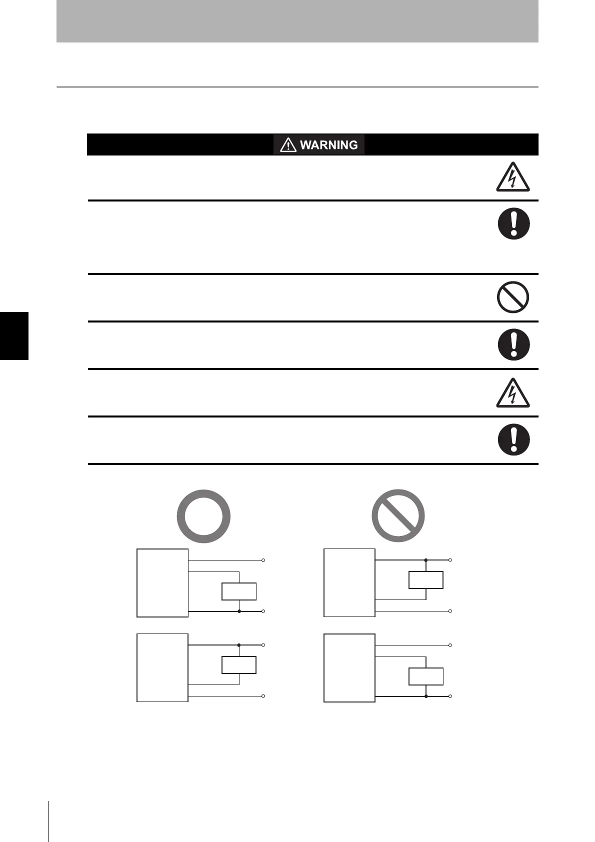
When using the PNP output, connect the load between the output and 0 V line. When
using the NPN output, connect the load between the output and +24 VDC line.
Connecting the load between the output and a different power supply line from the above
line will result in a dangerous condition because the operation mode of safety outputs are
reversed to "Dark-ON".
When using the PNP output, do not ground +24 VDC line. When using the NPN output,
do not ground 0 V line. Otherwise, a ground fault may turn the safety outputs ON,
resulting in a failure of stopping the machine.
Configure the system by using the optimal number of safety outputs that satisfy the
requirements of the necessary safety category.
Do not connect each line of the F3SG-SR to a DC power supply of higher than 24
VDC+20%. Also, do not connect it to an AC power supply. Failure to do so may result in
electric shock.
Make sure to perform wiring while the power supply is OFF.
+24 VDC
0 VDC
+24 VDC
0 VDC
Brown
Black, White
Blue
Receiver
Brown
Black, White
Blue
Load
Load
Receiver
+24 VDC
0 VDC
Brown
Black, White
Blue
Receiver
Load
+24 VDC
0 VDC
Brown
Black, White
Blue
Load
Receiver
[PNP]
[NPN]

 Loading...


