295
F3SG-SR
User’s Manual
Chapter5 Wiring
Wiring and Installation
E
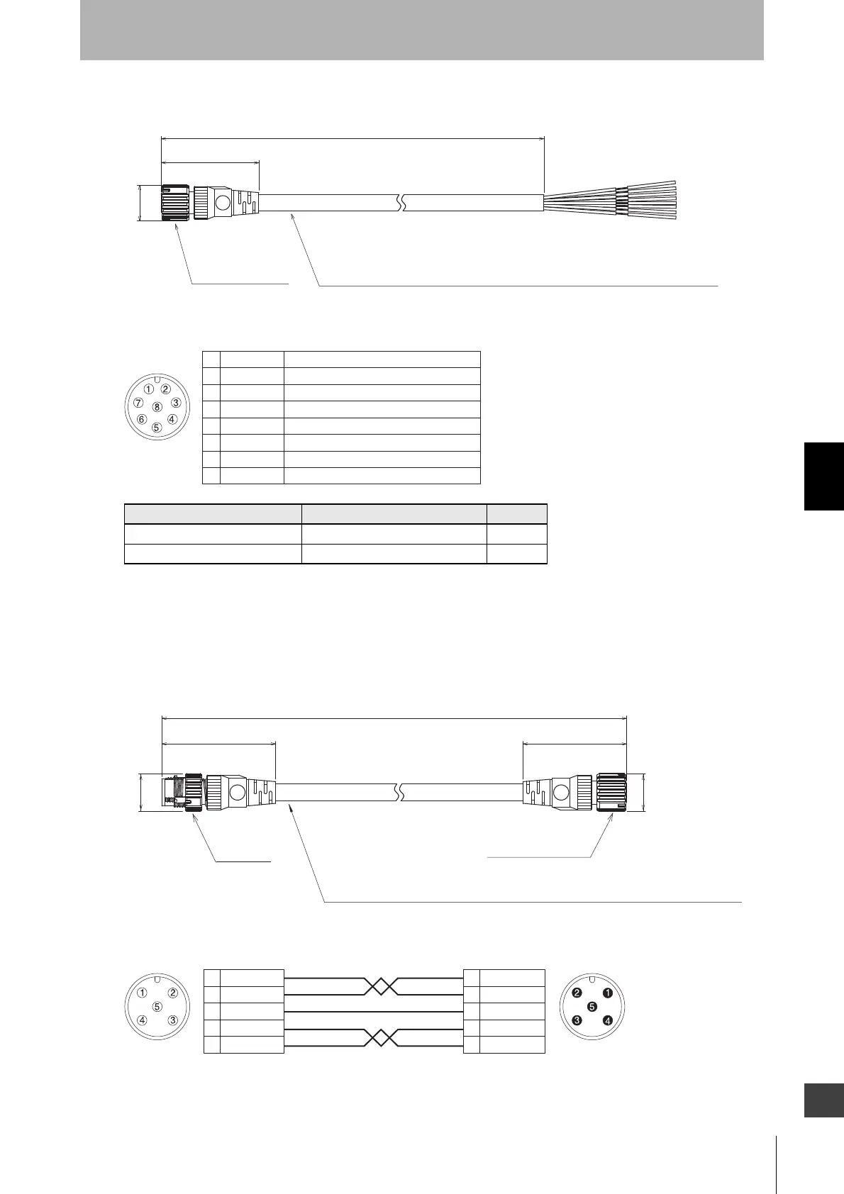
Extended Socket-Straight Cable for Receiver (F39-JG
A-D, sold separately)
<Internal wiring diagram>
5-4-3-4. Extended Plug-Socket Cable
Extended Plug-Socket Cable for Emitter: Cable for extension (F39-JGB-L,
sold separately)
<Internal wiring diagram>
Emitter cable (Gray) Receiver cable (Black) Length (L)
F39-JG3A-L F39-JG3A-D 3 m
F39-JG10A-L F39-JG10A-D 10 m
Insulated vinyl round cable, dia. 6.6, minimum bending radius R36, 8-wire
(Cross section of conductor: 0.32 mm
2
/insulator diameter: dia. 1.2 mm/AWG22)
dia.14.9
M12 IP67 connector
(Unit: mm)
L
40.7
Female
Connected to root cable or
Extended Plug-Socket Cable
Brown 24V/0V2
Blue 0V/24V7
Black OSSD 15
White
OSSD 2
6
Yellow RESET/EDM1
Red AUX8
Gray MUTE A/PRE-RESET/PSDI/COM(+)3
Pink MUTE B/COM(-)4
M12 IP67
connector
Insulated vinyl round cable, dia. 6.6, minimum bending radius R36, 5-wire (2-pair + 1)
(Cross section of conductor: 0.32 mm
2
/insulator diameter: dia. 1.2 mm)
(Unit: mm)
M12 IP67 connector
40.7
L
44.7
dia.14.9
dia.14.9
Brown
Blue
Black
White
Yellow
1
3
2
4
5
Connected to root cable or
Extended Plug-Socket Cable
Twisted pair wires are brown and blue, and white and yellow.
Connected to Extended Socket-Straight
Cable or Extended Plug-Socket Cable
Brown
Blue
Black
White
Yellow
1
3
2
4
5
Female
Male

 Loading...


