296
Chapter5 Wiring
F3SG-SR
User’s Manual
Wiring and Installation
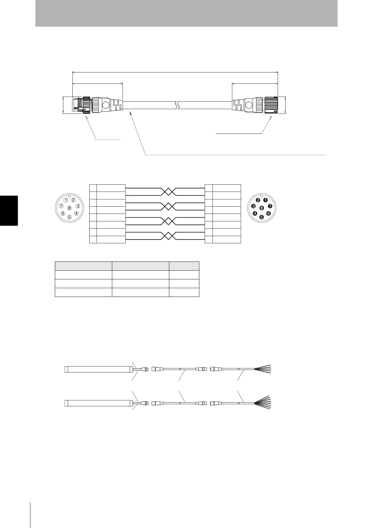
Extended Plug-Socket Cable for Receiver: Cable for extension (F39-JG
B-D, sold
separately)
<Internal wiring diagram>
If the length of the F39-JGA Single-Ended Cable is insufficient, use 1 or more F39-JGB Extended
Plug-Socket Cables to extend the length, as required. The total cable extension length of the root cable
must be 100 m max. (When the Intelligent Tap (F39-SGIT-IL3) is connected to the sensor, this applies
in the case of the rated power supply of 24 VDC or higher.)
<Connection example>
Emitter cable (Gray) Receiver cable (Black) Length (L)
F39-JG3B-L F39-JG3B-D 3 m
F39-JG10B-L F39-JG10B-D 10 m
F39-JG20B-L F39-JG20B-D 20 m
M12 IP67
connector
Insulated vinyl round cable, dia. 6.6, minimum bending radius R36, 8-wire (4-pair)
(Cross section of conductor: 0.32 mm
2
/insulator diameter: dia. 1.2 mm)
(Unit: mm)
M12 IP67 connector
40.7
L
44.7
dia.14.9
dia.14.9
Brown
Blue
Black
White
Yellow
Red
Gray
Pink
Blue
Black
White
Yellow
Red
Gray
Pink
2
7
5
6
1
8
3
4
Brown2
7
5
6
1
8
3
4
Connected to root cable or
Extended Plug-Socket Cable
Twisted pair wires are brown and blue, black and white, yellow and red, and gray and pink.
Connected to Extended Socket-Straight
Cable or Extended Plug-Socket Cable
Female Male
F39-JGR3K-L(Gray)
F39-JGB-L(Gray) F39-JGA-L(Gray)
F39-JGR3K-D(Black)
Emitter
Receiver
F39-JGB-D(Black)
Extended Plug-Socket CableRoot-Plug Cable for Extended Extended Socket-Straight Cable
F39-JGA-D(Black)

 Loading...


