322
Chapter6 Wiring Examples (for F3SG-SR)
F3SG-SR
User’s Manual
Input/Output Circuit and Applications
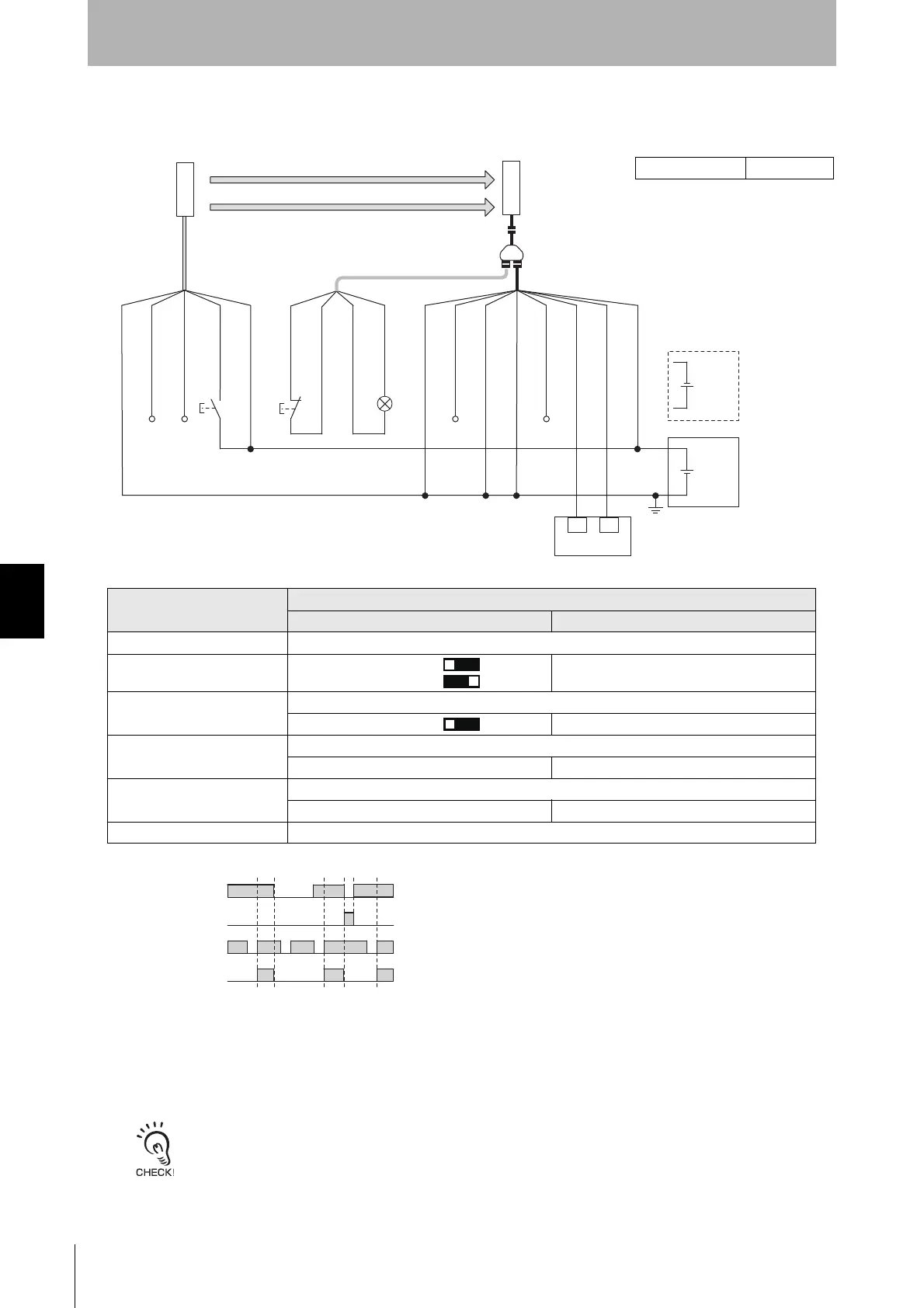
6-2-1-7. Manual Reset Mode with Reset Switch Connector
[Wiring Example]
• When using the Reset Switch Connector (F39-GCNY3), the following functions are not available.
- External Device Monitoring (EDM)
• When a functional earth is necessary, wire an earth cable according to the example in 6-2-1-1. Auto Reset Mode with
Optical Synchronization and EDM Unused. Also refer to 5-4-4. Functional Earth Connection for more information.
S2
S1
24 VDC
24 VDC
F39-JGC-L
F39-GCNY3
F39-JGR3K-D
XS5F-D42180-F
F39-JGA-D
IN1
IN2
L1
Wiring for NPN *1
OSSD 1 (Black)
OSSD 2 (White)
24V/0V (Brown)
TEST (Black)
Not used (White)
24V/0V (Brown)
0V/24V (Blue)
0V/24V (Blue)
AUX (Red)
MUTE B (Pink)
MUTE A (Gray)
RESET (Yellow)
0V/24V (Blue)
RESET (White)
24V/0V (Brown)
AUX (Black)
OPERATING
RANGE SELECT
INPUT (Yellow) *2
Emitter
Receiver
Safety controller
*3 *4
*5
Timing chart
Beam state: Unblocked
Blocked
Reset switch (S2)
Test switch (S1)
OSSD
S1: Test switch
S2: Lockout/interlock reset switch
L1: Lamp
: Indicates a switch position.
Function
Setting
DIP switch SD Manager 3
EDM EDM Disabled (factory default setting)
Interlock *6 Manual Reset [Start interlock] : Enable
[Restart interlock] : Enable
Operating Range Selection
Long : Open the OPERATING RANGE SELECT INPUT line of the emitter or connect the line to 24 VDC.
Long *6
[Operating Range Selection] : Long mode *6
Non-Muting system Perform wiring according to the wiring diagram.
N/A [Muting] : Disable *6
External Test used Connect the TEST line of the emitter to 24V/0V of the emitter via a test switch (NO contact). *7
N/A [External test signal inversion] : Disable
Optical Synchronization Open the COM(+) and COM(-) lines of the emitter.
㻠㻻㻺
㻡㻻㻺
*1. Reverse the polarity of the power supply when using in the NPN system.
Select a safety controller of PNP or NPN type according to the system of
your application.
*2. Connect the line to 0 VDC if Operating Range Selection is used in Short
Mode.
*3. Refer to 6-3. Connectable Safety Control Units for more information.
*4. The safety controller and the F3SG-SR must share the power supply or be
connected to the common terminal of the power supply.
*5. This is the case for a PELV circuit.
*6. Set the function with the DIP Switches on the Intelligent Tap or the SD
Manager 3, restore the settings to the F3SG-SR, and perform wiring
according to the wiring diagram.
*7. This wiring example shows light emission stop when connected to 24 VDC
with PNP setting, and light emission stop when connected to 0 VDC with
NPN setting. If TEST switch is not needed, refer to 2-6. External Test.
Intelligent Tap Needed

 Loading...


