316
Chapter6 Wiring Examples (for F3SG-SR)
F3SG-SR
User’s Manual
Input/Output Circuit and Applications
6-2.
Wiring Examples (for F3SG-SR)
Examples of a motor control system using the F3SG-SR are shown below. This chapter shows examples
equivalent to up to PLe, Category 4 (ISO 13849-1).
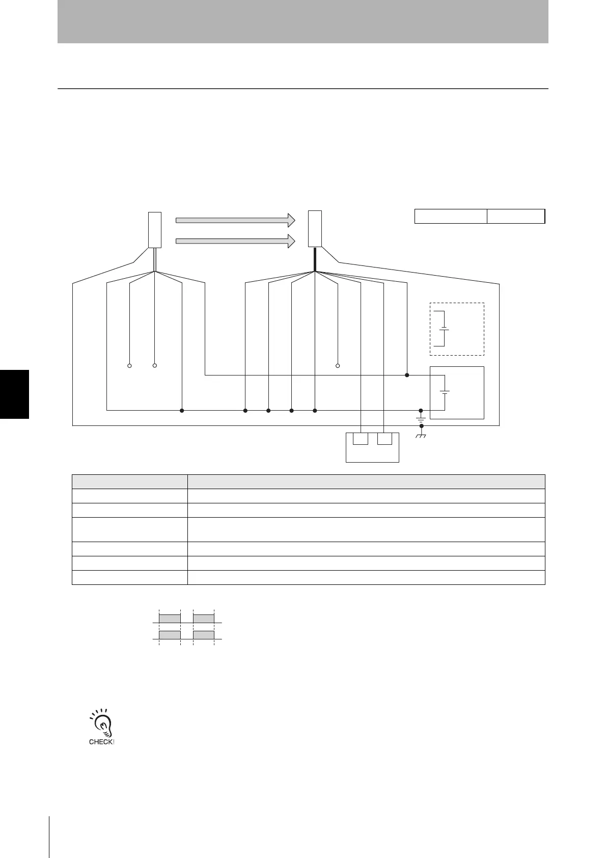
6-2-1. Non-Muting System Wiring Examples
6-2-1-1. Auto Reset Mode with Optical Synchronization and EDM Unused
[Wiring Example]
• Functional earth connection to the F3SG-SR housing is unnecessary when you use the F3SG-SR in a general
industrial environment where noise control or stable power supply is considered. However, when you use the F3SG-SR
in an environment where there may be excessive noise from surroundings or stable power supply may be interfered, it
is recommended the F3SG-SR be connected to functional earth.
• The wiring examples in later pages do not indicate functional earth. To use functional earth, wire an earth cable
according to the example above. Refer to 5-4-4. Functional Earth Connection for more information.
Beam state: Unblocked
Blocked
OSSD
OSSD 1 (Black)
OSSD 2 (White)
24V/0V (Brown)
OPERATING RANGE
SELECT INPUT (Yellow) *2
TEST (Black) *3
Not used (White)
24V/0V (Brown)
0V/24V (Blue)
0V/24V (Blue)
AUX (Red)
MUTE B (Pink)
MUTE A (Gray)
F39-JGC-L
F39-JGC-D
Timing chart
24 VDC
Wiring for NPN *1
*7
24 VDC
IN1
Safety controller
*5 *6
IN2
RESET/EDM
(Yellow) *4
Receiver
Emitter
*1. Reverse the polarity of the power supply when using in the NPN system. Select a safety
controller of PNP or NPN type according to the system of your application.
*2. Connect the line to 0 VDC if Operating Range Selection is used in Short Mode.
*3. Refer to 2-6. External Test for more information if External Test is used.
*4. Connect the line to 24V/0V (brown) of the receiver via a lockout reset switch (NC contact) if
Lockout Reset is used.
*5. Refer to 6-3. Connectable Safety Control Units for more information.
*6. The safety controller and the F3SG-SR must share the power supply or be connected to the
common terminal of the power supply.
*7. This is the case for a PELV circuit.
Function Setting
EDM EDM Disabled (factory default setting)
Interlock Auto Reset (factory default setting)
Operating Range Selection
Long : Open the OPERATING RANGE SELECT INPUT line of the emitter or connect the line to 24
VDC.
Non-Muting system Perform wiring according to the wiring diagram.
External Test not used Connect the TEST line of the emitter to 0V/24V of the emitter.
Optical Synchronization Do not connect the COM(+) and COM(-) lines of the of emitter and receiver with each other.
Intelligent Tap Not needed

 Loading...


