301
F3SG-SR
User’s Manual
Chapter5 Wiring
Wiring and Installation
E
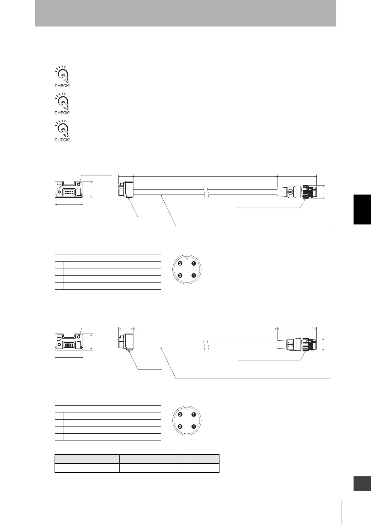
5-4-3-8. F3SG-RE Conversion Cable
Used to convert the wiring for F3SG-RE Safety Light Curtain to that for the F3SG-SR.
Do not connect the Conversion Cable for the following purposes. Failure to do so may result in failure.
1. Connecting with the F39-SGIT-IL3, F39-GCNY2 or F39-GCNY3
2. Connecting between the F3SG-SR's
Conversion Cables are only for PNP connection. To use for NPN, connect the 24 VDC line and the 0 VDC line in reverse.
There are the restrictions on the functions related to wiring when using Conversion Cables.
F3SG-RE Conversion Cable for Emitter (F39-JGR3K-RE-L, sold separately)
<Internal wiring diagram>
F3SG-RE Conversion Cable for Receiver (F39-JGR3K-RE-D, sold separately)
<Internal wiring diagram>
Emitter cable (Gray) Receiver cable (Black) Length
F39-JGR3K-RE-L F39-JGR3K-RE-D 0.3 m
Connector
M12 IP67 connector, 4-wire
Oil-resistant PVC-insulated round cable, dia. 6
minimum bending radius R5
(Cross section of conductor: 0.2 mm
2
/insulator diameter: dia. 1.1 mm)
44.7
14.9 dia.
300
31.6
18.5
2-M2.5 screw
16.4
(Unit: mm)
Connected to connector of F3SG-RE emitter cable
F3SG-RE
1
2
3
4
+24 VDC
Operating Range Select Input
0 VDC
Not used
Male
Connector
M12 IP67 connector, 4-wire
Oil-resistant PVC-insulated round cable, dia. 6
minimum bending radius R5
(Cross section of conductor: 0.2 mm
2
/insulator diameter: dia. 1.1 mm)
44.7
14.9 dia.
300
31.6
18.5
2-M2.5 screw
16.4
(Unit: mm)
Connected to connector of F3SG-RE receiver cable
F3SG-RE
1
2
3
4
+24 VDC
OSSD 2
0 VDC
OSSD 1
Male

 Loading...


