79
F3SG-SR
User’s Manual
Chapter2 Muting
System Operation and Functions
E
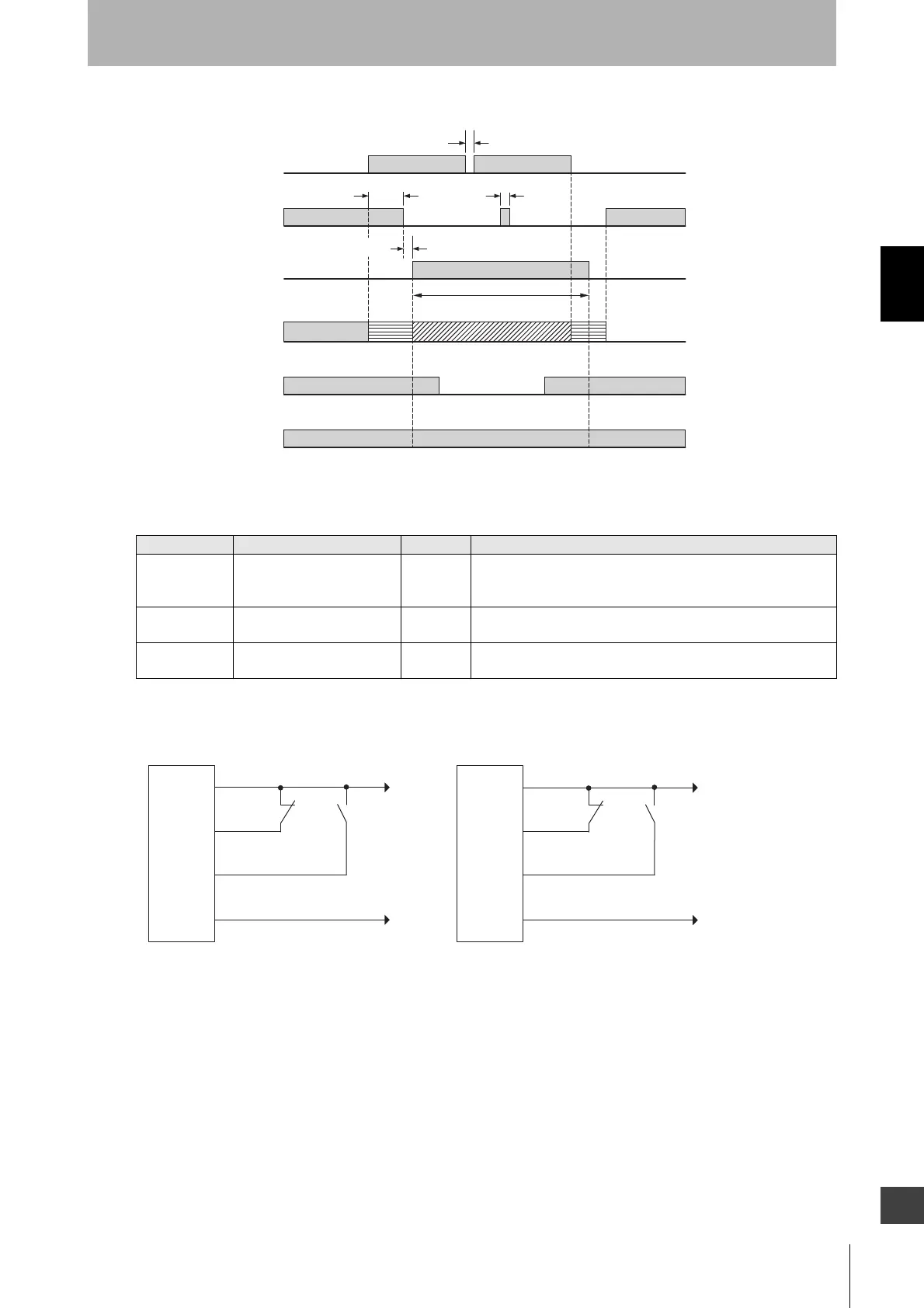
Timing chart
Basic wiring diagram
Variable Variable name Value Description
T1max Muting input time limit value
(maximum)
4 s Maximum time difference between muting inputs A and B.
If the time difference between muting inputs A and B is larger
than this value, a muting error occurs.
T2 Muting time limit 60 s The duration time of the Muting function. The MUTING state is
cancelled if it continues for longer than this time limit.
T3 Maximum allowable muting
signal interruption
0.1 s Maximum duration of a signal interruption allowed in muting
inputs A and B.
T1max: Muting input time limit value (maximum)
T2: Muting time limit
T3: Maximum allowable muting signal interruption
T3 (0.1 s) max.
T1max.
T3 (0.1 s) max.
80 ms max. *
T2 max.
Orange
blinking
Green blinkingGreen ON
Orange
blinking
* 102 ms max. when the
Intelligent Tap is connected
to the F3SG-SR.
ON
OFF
Unblocked
Blocked
OSSD
ON
OFF
Enabled
Disabled
ON
OFF
Muting input A
(Limit switch1)
Muting input B
(Limit switch2)
MUTING state
Beam state
ABI indicator
ON
OFF
+24 VDC
0V
PNP
NPN
S1 S2
0V
+24 VDC
MUTE A/PRE-RESET/PSDI/COM(+)
(Gray)
S1 S2
24V/0V (Brown)
MUTE B/
COM(-) (Pink)
MUTE A/PRE-RESET/PSDI/COM(+)
(Gray)
0V/24V (Blue)
S1, S2䠖Muting sensor
F3SG-SR
receiver
F3SG-SR
receiver
24V/0V (Brown)
MUTE B/
COM(-) (Pink)
0V/24V (Blue)

 Loading...


