115
F3SG-SR
User’s Manual
Chapter2 Area Beam Indicator (ABI)
System Operation and Functions
E
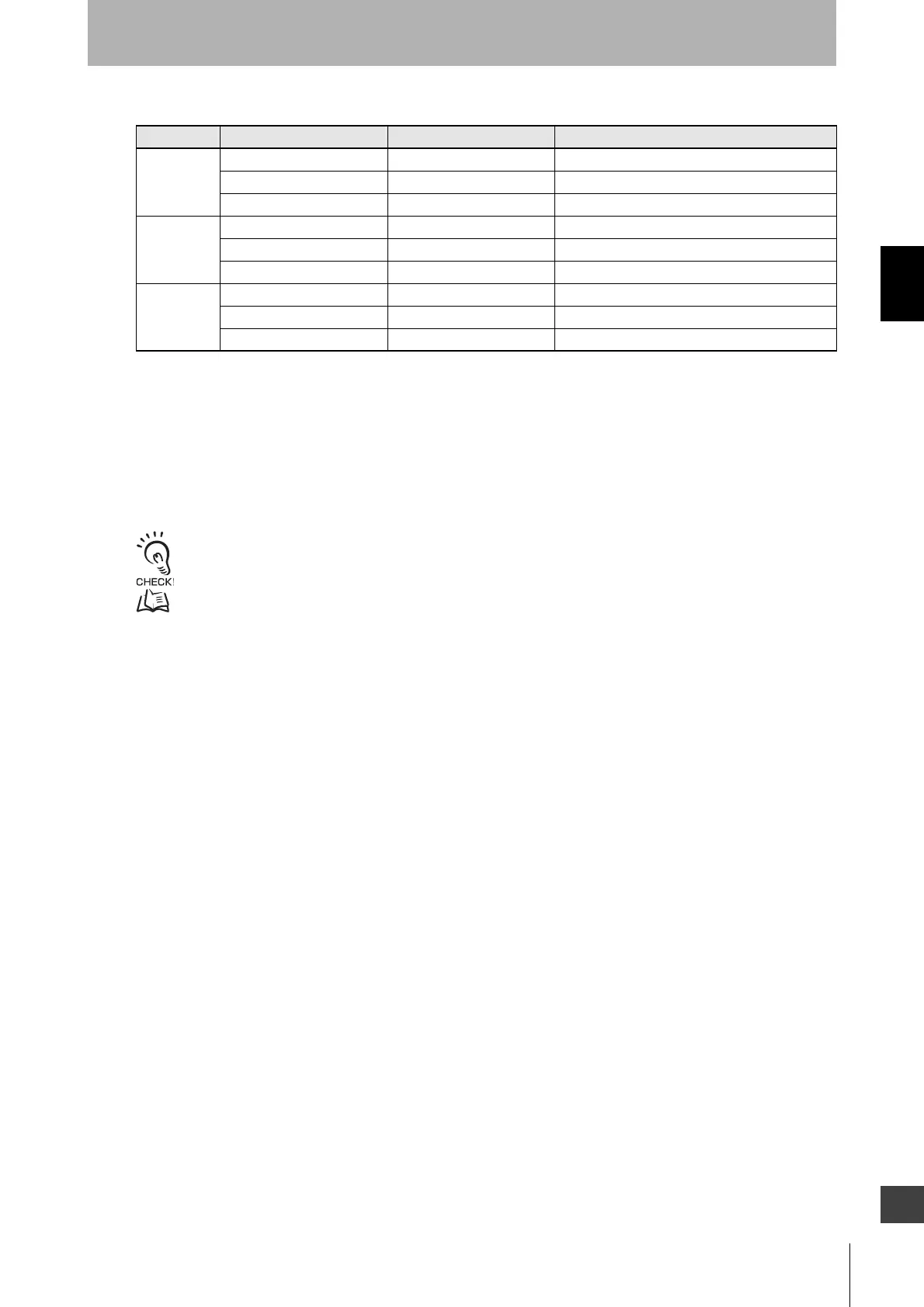
Setting when selecting output information
*1. It is unable to use input signal linkage and the muting function together. To enable the setting of input signal linkage, disable
the muting function.
In addition, for the following functions, setting parameters are kept individually in each case that the muting function is set
enabled or disabled. When changing the muting state from enabled to disabled or vice versa using SD Manager 3, confirm
the setting of the respective functions again.
Functions influenced:
External device monitoring, start interlock, restart interlock, and auxiliary output
*2. Configurable items are equal to the information assigned to the auxiliary output. For the details of the information assigned to
the auxiliary output, refer to Section 2-12. “Auxiliary Output.”
It is recommended that the Position 2 of the DIP Switch be set at OFF (DIP Switch Disabled).
For the details of change of setting parameters using SD Manager 3, refer to Chapter 4 Setting with SD Manager 3.
ABI pattern Function Initial value Configurable item
Red Output operation mode Safety output information *2
Inverted signal output Enabled Enabled/disabled
Output pattern Solid-ON Solid-ON, ON 1 time, ON 2 times, and ON 3 times
Orange Output operation mode Stable state information *2
Inverted signal output Enabled Enabled/disabled
Output pattern ON 1 time Solid-ON, ON 1 time, ON 2 times, and ON 3 times
Green Output operation mode Safety output information *2
Inverted signal output Disable Enabled/disabled
Output pattern Solid-ON Solid-ON, ON 1 time, ON 2 times, and ON 3 times

 Loading...


