153
F3SG-SR
User’s Manual
Chapter3
IO-Link
Setting with Intelligent Tap
E
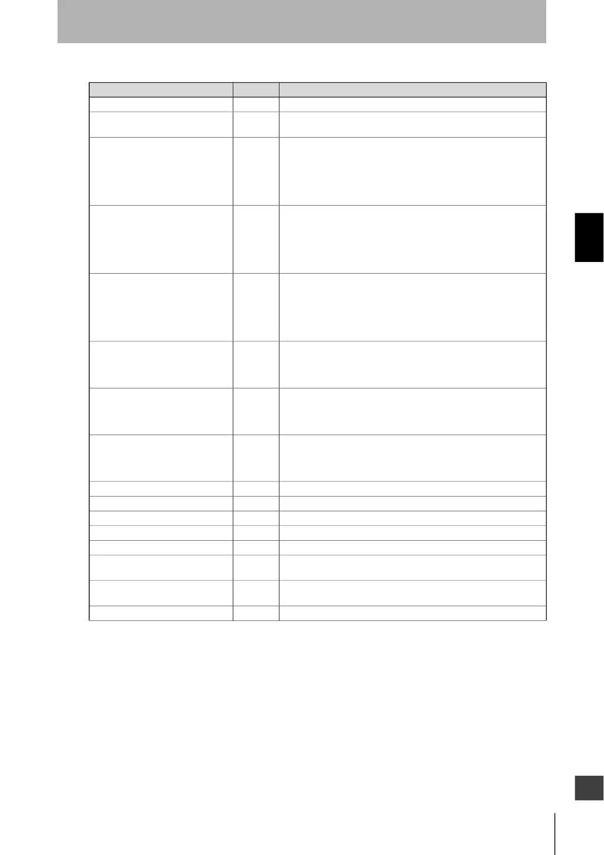
The table below lists the data size and descriptions of the process data items.
* It is necessary to change the value in the setting of [Stable Light Threshold Adjustment] of the SD Manager 3.
Refer to 2-24. Stable Light Threshold Adjustment and 4-3-5-2. Stable Light Threshold Adjustment for more information on the
stable light threshold value.
Name Data size Description
Power supply voltage 16 bits Power supply voltage value for Receiver being supplied. (VDC)
Sequence error information 1 bit 1: Under muting sequence error state or interlock sequence error state.
0: No muting sequence error state or interlock sequence error state.
Light level diagnosis information
(Channel 1)
1 bit 1: When the single F3SG-SR or the primary sensor in cascaded
connection is unblocked and light intensity is within a range from 100%
to 170% (factory default setting*) of ON-threshold for 10 s or longer.
0: When the single F3SG-SR or the primary sensor in cascaded
connection is blocked and light intensity is lower than 100% of ON-
threshold for 10 s or longer.
Light level diagnosis information
(Channel 2)
1 bit 1: When the 1st secondary sensor in cascaded connection is unblocked
and light intensity is within a range from 100% to 170% (factory default
setting*) of ON-threshold for 10 s or longer.
0: When the 1st secondary sensor in cascaded connection is blocked
and light intensity is lower than 100% of ON-threshold for 10 s or
longer.
Light level diagnosis information
(Channel 3)
1 bit 1: When the 2nd secondary sensor in cascaded connection is unblocked
and light intensity is within a range from 100% to 170% (factory default
setting*) of ON-threshold for 10 s or longer.
0: When the 2nd secondary sensor in cascaded connection is blocked
and light intensity is lower than 100% of ON-threshold for 10 s or
longer.
Instantaneous Block Detection
Information (Channel 1)
1 bit 1: When the single F3SG-SR or the primary sensor in cascaded
connection stops accidentally due to instantaneous blocking.
0: When the single F3SG-SR or the primary sensor in cascaded
connection is not blocked.
Instantaneous Block Detection
Information (Channel 2)
1 bit 1: When the 1st secondary sensor in cascaded connection stops
accidentally due to instantaneous blocking.
0: When the 1st secondary sensor in cascaded connection is not
blocked.
Instantaneous Block Detection
Information (Channel 3)
1 bit 1: When the 2nd secondary sensor in cascaded connection stops
accidentally due to instantaneous blocking.
0: When the 2nd secondary sensor in cascaded connection is not
blocked.
Safety output status 1 bit 1: ON, 0: OFF
Auxiliary output status 1 bit 1: ON, 0: OFF
Mute A input status 1 bit 1: ON, 0: OFF
Mute B input status 1 bit 1: ON, 0: OFF
RESET/EDM/Override input status 1 bit 1: ON, 0: OFF
Intelligent Tap Lockout information 1 bit 1: Intelligent Tap is in LOCKOUT state
0: Intelligent Tap is not in LOCKOUT state.
Sensor or Intelligent Tap lockout
information
1 bit 1: Sensor or Intelligent Tap is in LOCKOUT state
0: Nether the Sensor or Intelligent Tap is in LOCKOUT state.
Reserved 4 bytes 0

 Loading...


