163
F3SG-SR
User’s Manual
Chapter4 Overview and Specifications
Setting with SD Manager 3
E
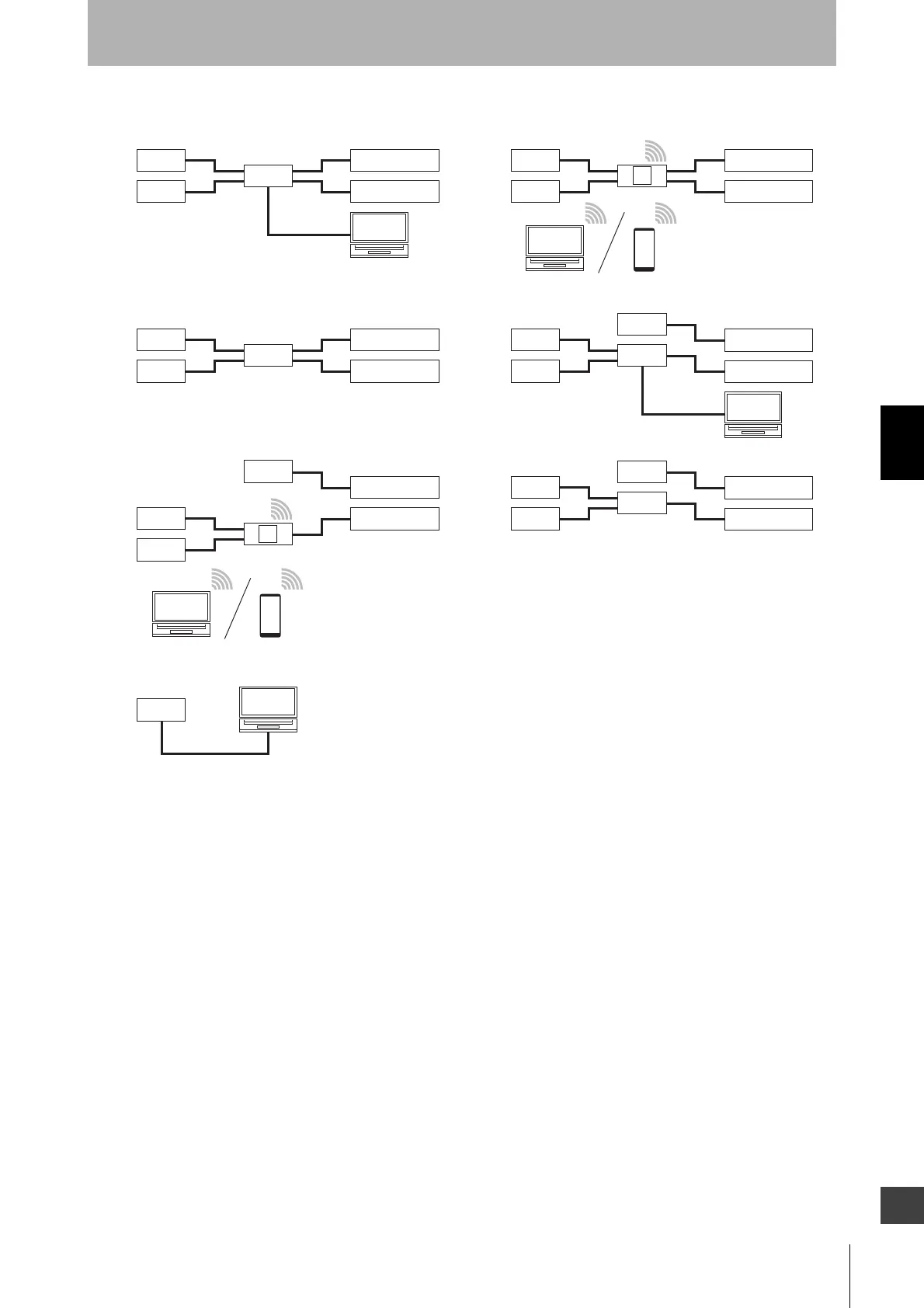
For the patterns (1) and (4), turn the power on and start the SD Manager 3 on the PC.
For the pattern (7), the power is supplied from the PC to the Intelligent Tap.
When connecting the emitter and receiver with the Intelligent Tap as shown in the above patterns (2) to
(4), it is possible to make settings to the emitter and receiver and perform IO-Link communication,
Backup and Restoration.
If the emitter is not connected with the Intelligent Tap like patterns (5) to (7) above, there are the
following restrictions.
• As synchronization method, only the optical synchronization is usable.
• It is unable to configure the following function using the DIP Switch on the Intelligent Tap.
Operating range selection
• It is unable to configure the following functions using SD Manager 3.
External test, operating range selection, lamp, area beam indicator (ABI), and vibration detection
• It is unable to monitor the emitter using the configuration tools.
• The backup and restoration functions of the emitter are not usable.
• The information of the emitter cannot be obtained via IO-Link.
Before connecting with each device, confirm that the power of the F3SG-SR and Intelligent Tap is
OFF. After connection is completed, turn ON the power and start up the F3SG-SR and Intelligent Tap.
(7)
(3)
(1)
(6)
(4)
(2)
(5)
PC
IT
IT: Intelligent Tap
BT: Bluetooth
®
communication unit
IO-Link: IO-Link Master
Power
supply
IO-Link
Receiver
Emitter
IT
PC
Power
supply
IO-Link
Receiver
Emitter
IT
Power
supply
Power
supply
IO-Link
IT
Receiver
Emitter
PC
Power
supply
Power
supply
IO-Link
IT
Receiver
Emitter
PC
Power
supply
IO-Link
Receiver
Emitter
IT BT
PC
Power
supply
Power
supply
IO-Link
Receiver
Emitter
IT BT

 Loading...


