223
F3SG-SR
User’s Manual
Chapter4 Monitoring with SD Manager 3
Setting with SD Manager 3
E
Readout Information
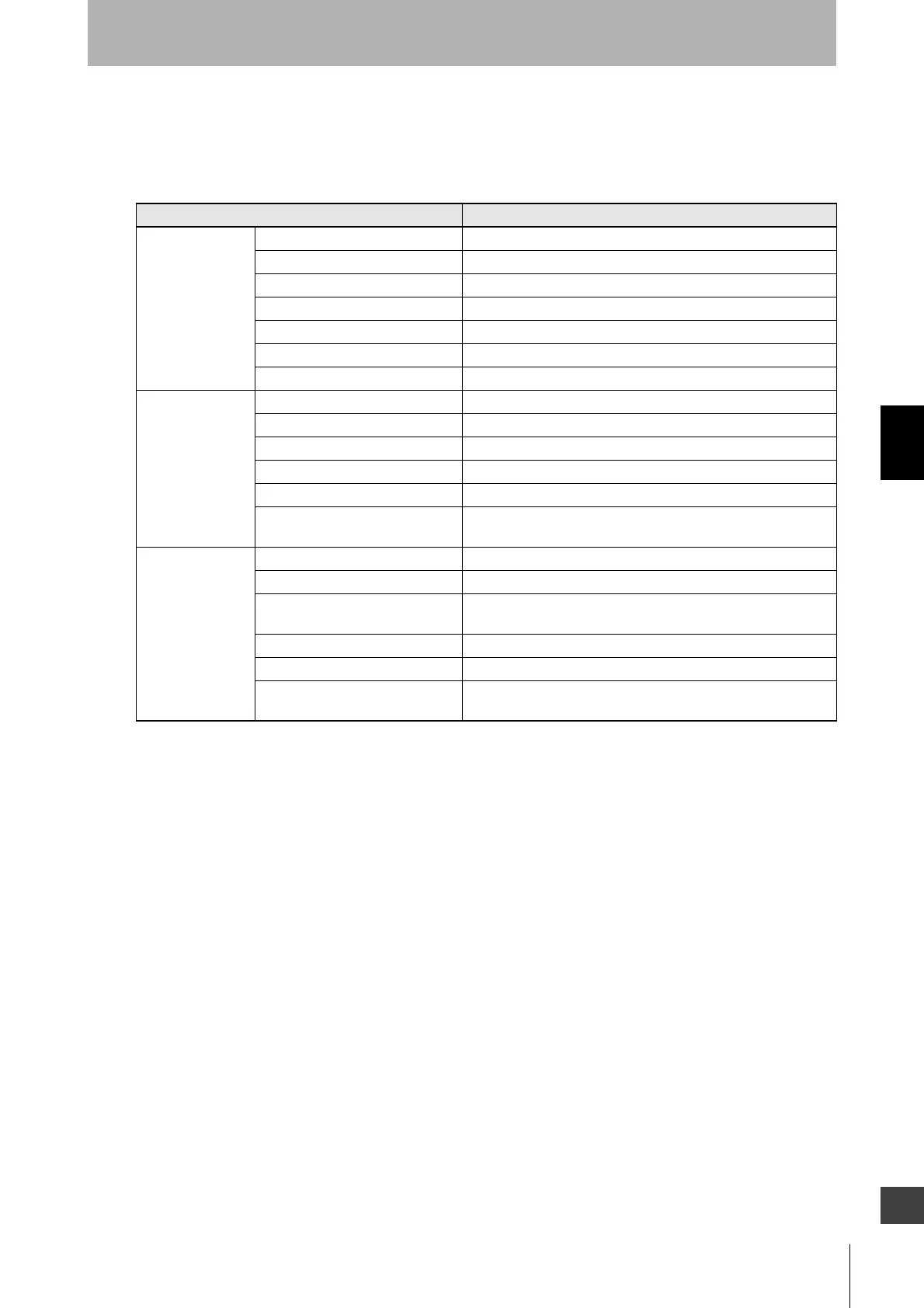
The user can view the following information related to a receiver or emitter.
If more than one sensor is cascaded in series, information on all the cascaded sensors is viewed
together.
Information Description
External wiring Power Supply The power supply voltage in the power-on status is displayed.
OSSD 1 (Black) Linked with safety output 1
OSSD 2 (White) Linked with safety output 2
RESET (Yellow) Linked with Reset/EDM/Override input
AUX (Red) Linked with auxiliary output
MUTE A (Gray) Linked with MUTE A/Pre-Reset input/PSDI input
MUTE B (Pink) Linked with MUTE B input
Sensor Scan code Displays Scan Code configured
EDM Displays EDM configuration
Interlock/Pre-Reset/PSDI Displays Interlock/Pre-Reset/PSDI mode configured
Fixed/Floating Blanking Displays Fixed/Floating Blanking configured
PNP/NPN Displays output mode (PNP/NPN) configured
DIP Enable/Disable Displays whether the settings by the DIP Switches are enabled or
disabled.
Operating Status Muting information Linked with muting status
Override information Linked with override status
Sequence error information Linked with muting sequence error status or interlock sequence
error status
Safety output information Linked with safety output
Push-SW information Linked with the input signal of Push Switch
Blanking beam unblocked
information
Linked with the state where the blanking beam is unblocked

 Loading...


