255
F3SG-SR
User’s Manual
Chapter5 Installation Considerations
Wiring and Installation
E
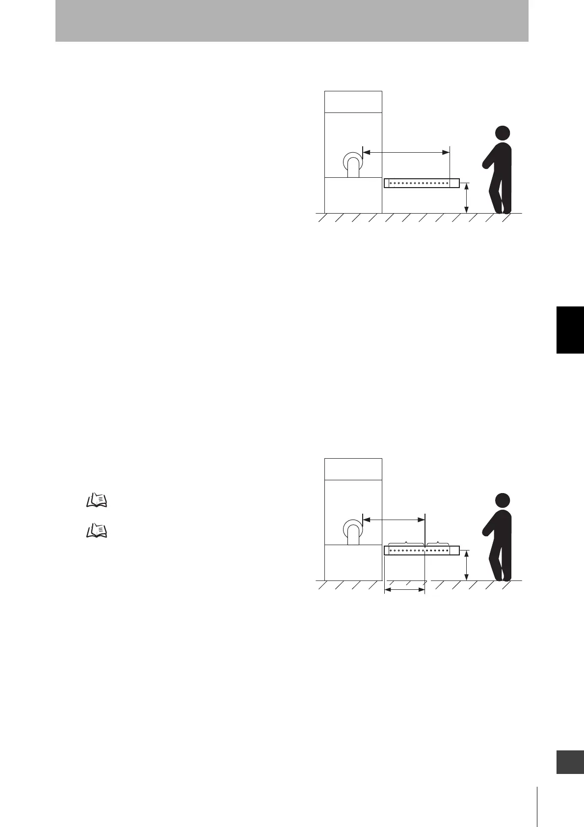
Detection Zone Parallel to Direction of Approach
Use K = 1,600 mm/s and C = (1200 - 0.4 x H) in
formula (1) for calculation. Note that C must not be
less than 850 mm.
S = 1,600 mm/s x (Tm + Ts) + 1200 - 0.4 x H
• S = Safety distance (mm)
• Tm = Machine's response time (s)
• Ts = Response time of the F3SG-SR from ON to
OFF (s)
• H = Installation height (mm)
Note that H must satisfy:
1000 ≥ H ≥ 15 (d - 50 mm) ≥ 0mm
Also, you must include a hazardous condition under which a person may go through under a detection
zone if H exceeds 300 mm (200 mm for other purpose than industrial use) into risk assessment.
[Calculation example]
When Tm = 0.05 s, Ts = 0.008 s, and d = 14 mm:
S = 1,600 mm/s x (0.05 s + 0.008 s) + 1200 - 0.4 x 500 mm
= 1092.8 mm
When a warning zone is configured as in the figure, you must calculate L, a distance from an end of
casing to a detection zone, using a formula below:
L = (Total number of F3SG-SR beams - number of warning zone beams - 1) x P + 10
• P: Beam Gap (mm)
Refer to 1-6-1. List of Models and Response Times for
total number of F3SG-SR beams.
Refer to 1-5. Ratings and Specifications for beam gap.
+
Safety distance (S)
Hazard
H
Safety
distance (S)
Hazard
Distance L from casing end
to detection zone
Detection
zone
Warning
zone

 Loading...


