266
Chapter5 Dimensions
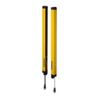
F3SG-SR
User’s Manual
Wiring and Installation
Side Mounting
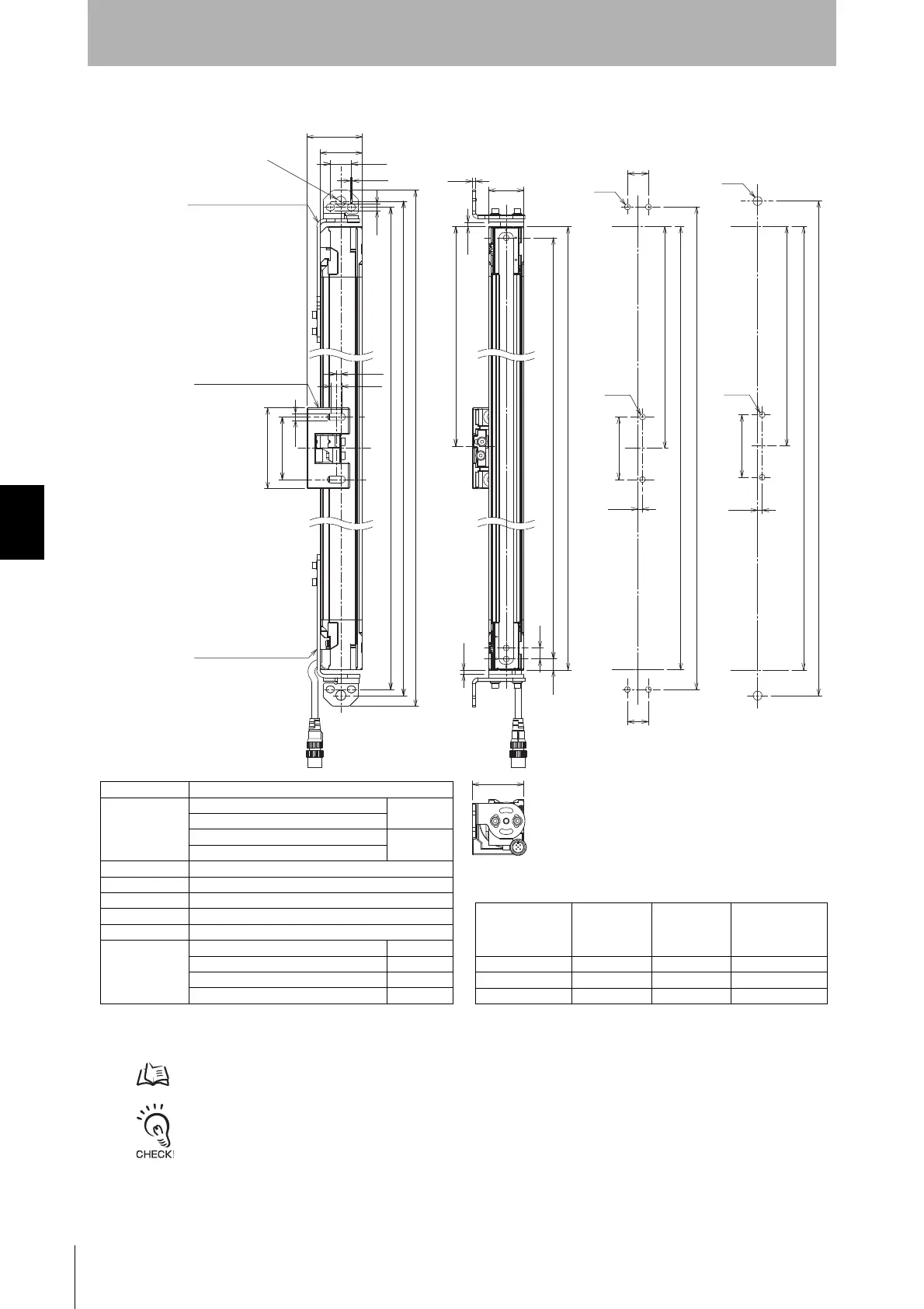
5-3-4-4. Mounting with Adjustable Top/Bottom Brackets (F3SJ, F3SN Adapter) (F39-LSGTB-SJ) and Adjustable Side-
Mount Brackets (Intermediate Brackets) (F39-LSGA)
- Use the brackets of specified quantities and locations according to the dimensions. The other brackets than described
above may not meet the specified ratings and performance.
- When you use the sensor in a situation where the sensor is under a load, increase the number of the brackets used.
- The Adjustable Top/Bottom Bracket and Adjustable Side-Mount Bracket allow beam alignment after fixing the bracket to
a wall surface. The angle adjustment range of the Adjustable Top/Bottom Brackets is ±22.5°. The angle adjustment
range of the Adjustable Side-Mount Brackets is ±15°.
<Screw for Adjustable
Top/Bottom Bracket: M8 *1>
<Screw for Adjustable
Top/Bottom Bracket: M5 *1>
46.7
2-M5
or M6
C
F
56.5
4.2
H
2-M8
19
19
56.5
4.2
F
C
G
4-M5
2-M5
or M6
3.2
32
F
C(Protective height)
N1
N2
10
P
D
5.8
6.3
1.7
9 dia.
4.2
56.5
G
H
19
38
73
10
50
I
4.2
H
Adjustable Side-Mount
Bracket (F39-LSGA)
Adjustable Top/Bottom
Bracket (F39-LSGTB-SJ)
Adjustable Top/Bottom
Bracket (F39-LSGTB-SJ)
[ Unit : mm ]
*1. Adjustable Side-Mount Bracket: M5 or M6
*2. For the model of protective height of 0160, the numbers corresponding to dimensions N1 and N2 are 20 to 30.
*3. The number of brackets required to mount either one of emitter and receiver.
Dimension C
4-digit number of the type name (Protective height:
)
Dimension D
F3SG-SR-14
C-20
F3SG-SR25
F3SG-SR-45
C-40
F3SG-SR-85
Dimension G C+27.2+N1+N2
Dimension H C+38+N1+N2
Dimension I C+58+N1+N2
Dimension N1 0 to 30 *2
Dimension N2 0 to 30 *2
Dimension P
F3SG-SR-14 10
F3SG-SR-25 20
F3SG-SR-45 40
F3SG-SR-85 80
Protective height
(Dimension C)
Number of
Adjustable
Top/Bottom
Bracket *3
Number of
Intermediate
Bracket *3
Dimension F
0160 to 0840 2 0 -
0880 to1680 2 1 1000 mm max.
1760 to 2480 2 2 1000 mm max.

 Loading...