311
F3SG-SR
User’s Manual
Chapter5 Cascade Connection
Wiring and Installation
E
When Using the F39-JGR12L Side-by-side Cascading Cable (sold separately)
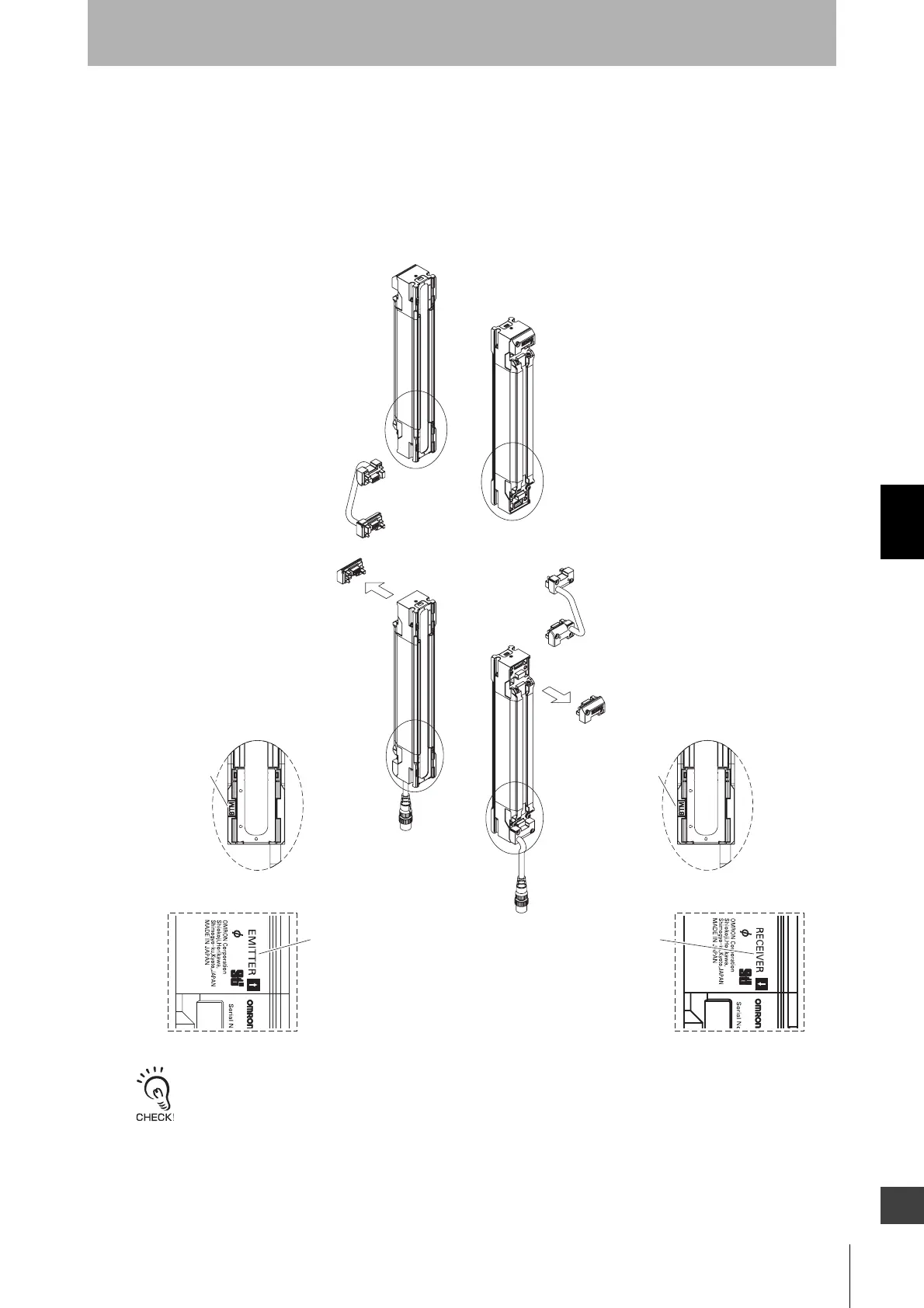
1. Remove the caps from the primary sensor. Loosen the screw (M2.5 cross-head) to remove the cap.
2. Connect the primary sensor and the secondary sensor with the F39-JGR12L Side-by-side Cascading
Cable (sold separately). Do not connect the F3SG-SR upside down. In the figure below, the side with
the mark "BTM" on the plastic part of the F3SG-SR must come to the down side.
- When attaching a cable or cap, securely fasten the screws (M2.5, recommended torque: 0.35 N•m).
Failure to do so may cause the cable/cap to come loose, leading to deterioration of the protective functions.
- Attaching/detaching of the cap and the Cascading Cable may cause misalignment of rubber grommet in the
connector assembly. Press the grommet to the bottom of the connector and attach the connector to the sensor
again.
F3SG
-L
F3SG-
D
1.
1.
2.
2.
End Cap
End Cap
Marking on the side (Receiver)
Marking on the side (Emitter)
"EMITTER" mark
Marking on plastic part
Marking on plastic part
Side-by-side
Cascading Cable
F39-JGR12L-L
Side-by-side
Cascading Cable
F39-JGR12L-D
<Secondary sensor>
<Primary sensor>
"RECEIVER" mark
"BTM" mark"BTM" mark
Root-Plug Cable for
Extended for Receiver
F39-JGR3K-D
Root-Plug Cable for
Extended for Emitter
F39-JGR3K-L

 Loading...


