32
Chapter2 Combination of Functions
F3SG-SR
User’s Manual
System Operation and Functions
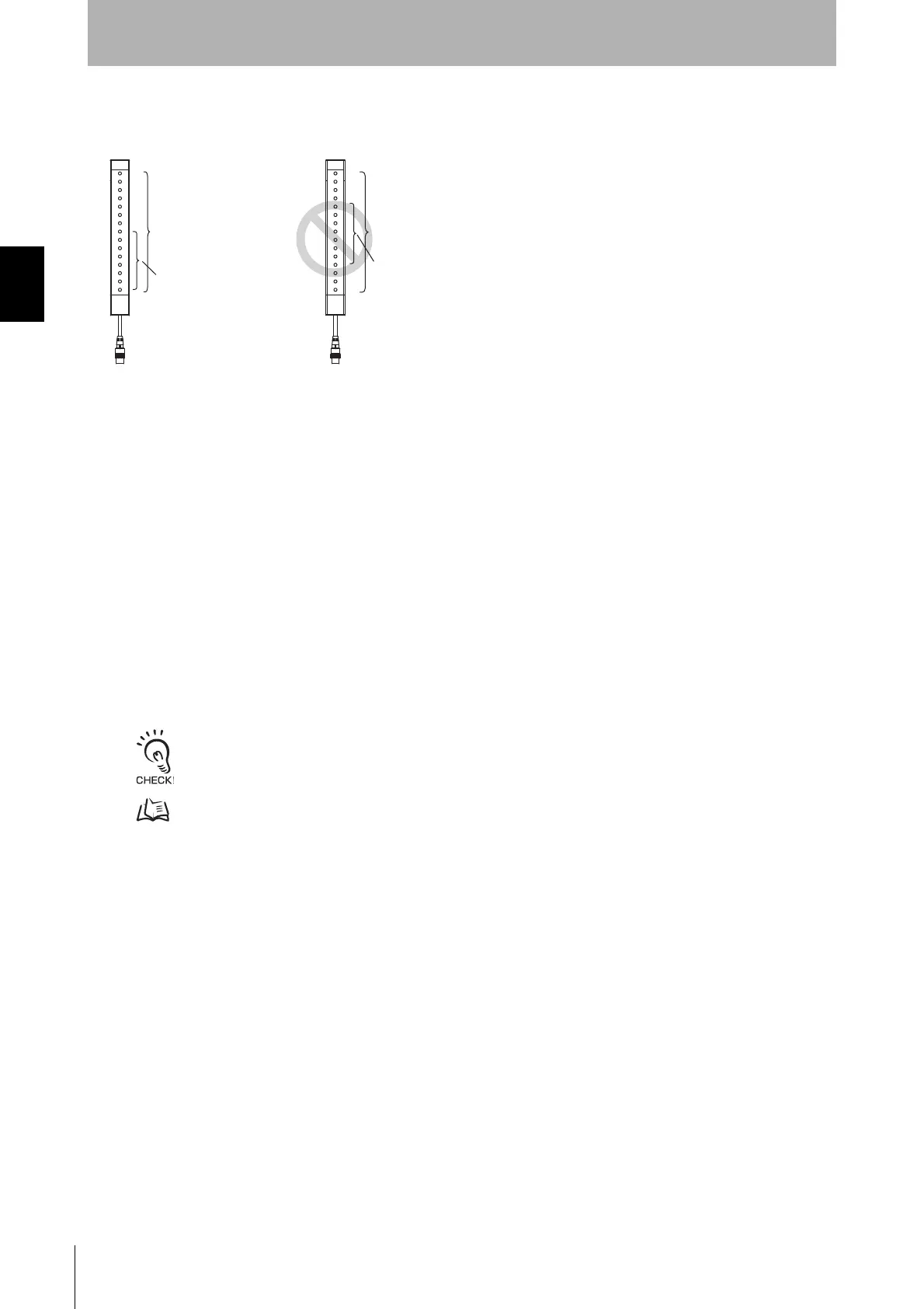
*2. When the Fixed Blanking and Floating Blanking are selected, the top or bottom beam must be included in the Fixed Blanking zone, as
shown in the left figure below. It is not allowed to set the Fixed Blanking zone not to cover the top or bottom beam, as shown in the
right figure below. It is also not allowed to set a Fixed Blanking zone to split a Floating Blanking zone.
*3. The monitoring temporarily disabling function by the external wiring of floating blanking is not usable together.
*4. This is the function to operate the area beam indicator (ABI) using muting input A/B. For details, refer to 2-22. Area Beam Indicator
(ABI).
*5. This is the function to use the teach-in input of fixed blanking or floating blanking by the [Push-SW or external wiring]. For details, refer
to 4-3-2-3. Teach-in Input
Considerations for enabling and disabling Muting function with SD Manager 3
Setting parameters of the following functions is saved according to the state where the Muting function
is enabled and disabled, respectively. After changing the Muting function from Enable to Disable or
from Disable to Enable, check the settings of these functions again.
Affected functions:
• External Device Monitoring (EDM)
• Start Interlock
• Restart Interlock
• Auxiliary Output
It is recommended that the Position 2 of the DIP Switch be set at OFF (DIP Switch Disabled).
Refer to the Setting with Configuration Tool sections of the affected functions in Chapter 2 System Operation and
Functions for more information on the setting parameters.
Floating
blanking zone
Fixed blanking
zone
Floating
blanking zone
Fixed blanking
zone

 Loading...


