46
Chapter2 Interlock
F3SG-SR
User’s Manual
System Operation and Functions
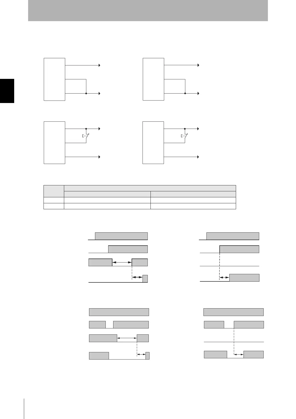
Basic wiring diagram
• Auto Reset mode
• Manual Reset mode
The table below shows the relation between the ON/OFF states and external lines.
Timing chart
• Start Interlock
• Restart Interlock
* The minimum pressing time of reset switch can be changed using SD Manager 3.
Input
External Connection
PNP NPN
ON Vs-3 V to Vs 0 to 3 V
OFF 0V to 1/2 Vs, or open 1/2 Vs to Vs, or open
+24 VDC
0V
PNP
0V
+24 VDC
NPN
24V/0V (Brown)
RESET/EDM (Yellow)
0V/24V (Blue)
F3SG-SR
receiver
F3SG-SR
receiver
24V/0V (Brown)
RESET/EDM (Yellow)
0V/24V (Blue)
+24 VDC
0V
PNP
S1
0V
+24 VDC
NPN
S1
24V/0V (Brown)
RESET/EDM (Yellow)
0V/24V (Blue)
S1: Lockout or interlock reset switch
24V/0V (Brown)
RESET/EDM (Yellow)
0V/24V (Blue)
F3SG-SR
receiver
F3SG-SR
receiver
Power
Beam state
RESET
OSSD
ON
OFF
ON
OFF
Unblocked
Blocked
Beam state
Unblocked
Blocked
ON
OFF
Power
RESET
OSSD
ON
OFF
ON
OFF
ON
OFF
Start Interlock: Enabled Start Interlock: Disabled
100 to 500 ms or longer
500 ms or less
Toff x 10 ms or less
Beam state
RESET
OSSD
ON
OFF
ON
OFF
Unblocked
Blocked
Beam state
Unblocked
Blocked
RESET
OSSD
ON
OFF
ON
OFF
Restart Interlock: Enabled Restart Interlock: Disabled
Toff: ON to OFF response time
ON
OFF
Power
ON
OFF
Power
100 to 500 ms or longer
500 ms or less
Toff x 5 ms or less

 Loading...


