52
Chapter2 PSDI
F3SG-SR
User’s Manual
System Operation and Functions
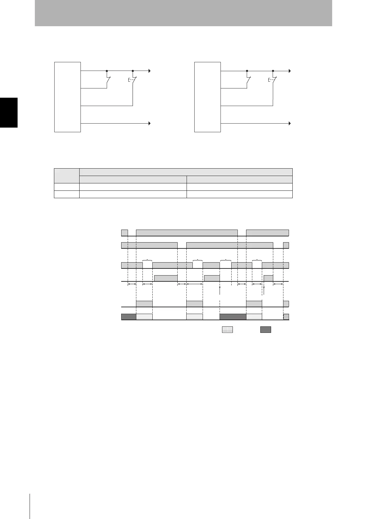
Basic wiring diagram
The table below shows the relation between the ON/OFF state and external connection.
Timing chart
Input
External connection
PNP NPN
ON Vs-3 V to Vs 0 to 3 V
OFF 0V to 1/2 Vs, or open 1/2 Vs to Vs, or open
DC24V
0V
PNP
S2
S2: Press position confirmation switch
S1
0V
+24 VDC
NPN
S2
S1
S1: Reset switch
24V/0V (Brown)
PSDI input (gray)
Reset input/external relay monitor input (yellow)
0V/24V (Blue)
F3SG-SR
receiver
24V/0V (Brown)
PSDI input (gray)
Reset input/external relay monitor input (yellow)
0V/24V (Blue)
F3SG-SR
receiver
T1: Minimum pressing time of reset switch, configurable by 100 ms in a range of 100-500 ms
T2: Minimum break time (300 ms)
T3: Minimum pressing time of press position switch. T3 = T1
T4: Wait time until single break is complete (30 s or less)
*1. When the machine is stopped by unintended block in the middle of pressing of parts, operation of the reset switch (S1)
and then a single dummy break are needed for reinitiation of the machine cycle.
*2. When Auxiliary Output is set to PSDI Information by the SD Manager 3.
T1
min.
T1
min.
T2
min.
Dummy
break*
1
Unintended
break
Feeding
parts
Feeding
parts
T3
min.
T3
min.
T4
Machine stops Machine restarts
T2
min.
Single Break
Reset switch (S1)
Press position
switch (S2)
OSSD
AUX*
2
SEQ indicator
(yellow)
Beam state
Unblocked
Blocked
ON
OFF
ON
OFF
ON
OFF
ON
OFF
ON
OFF
ON 1 time Solid-ON

 Loading...


