EasyManuals Logo

Panasonic FP Series User Manual

Panasonic FP Series
1345 pages
To Next Page IconTo Next Page
To Previous Page IconTo Previous Page
Page #1019 background imageLoading...
Page #1019 background image
Program execution control instructions
1018
Part III FP Instructions
PLC types
Availability of ICTL (see page 1327)
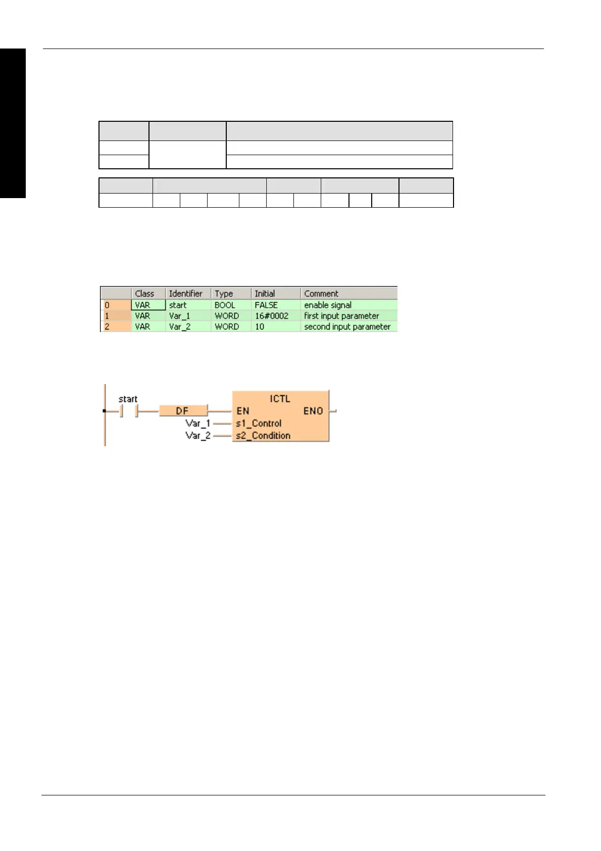
Variable Data type Function
s1 Interrupt control data setting
s2
ANY16
Interrupt condition setting
For Relay T/C Register Constant
s1, s2 - WY WR WL SV EV DT LD FL dec. or hex.
Data types
Operands
Example
In this example, the same POU header is used for all programming languages. For an example
using IL (instruction list), please refer to the online help.
POU header
All input and output variables used for programming this function have been declared in the POU
header.
Body
The interval for executing the periodic interrupt is specified as 100ms (10ms time base selected)
when the rising edge of start is detected.
LD

Table of Contents

Other manuals for Panasonic FP Series

Questions and Answers:

Question and Answer IconNeed help?

Do you have a question about the Panasonic FP Series and is the answer not in the manual?

Panasonic FP Series Specifications

General IconGeneral
MountingDIN rail
TypePLC
Communication InterfaceRS-232, RS-485, Ethernet (depending on model)
Input Voltage100-240V AC or 24V DC (depending on model)
Output TypeRelay, Transistor
I/O PointsVaries by model
Operating Temperature0°C to 55°C
DimensionsVaries by model
WeightVaries by model

Related product manuals