Arithmetic instructions
475
Part III FP Instructions
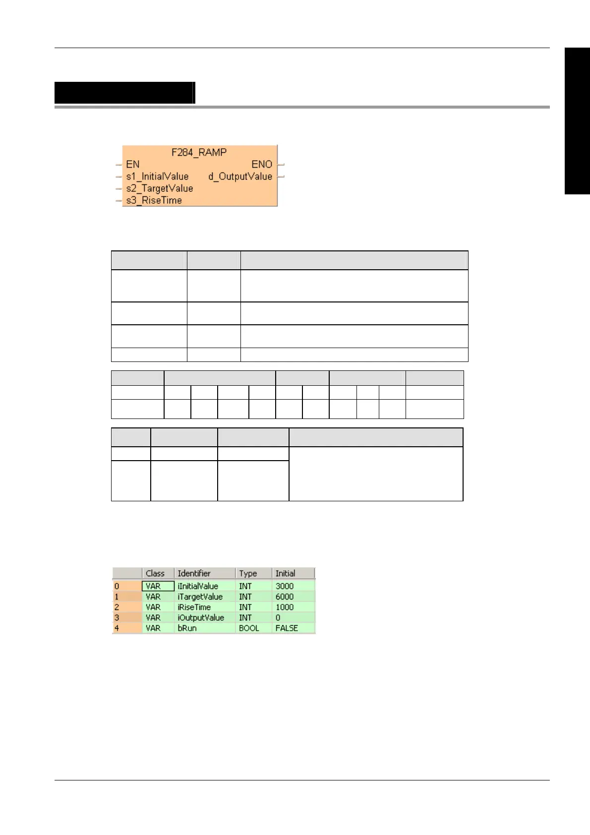
F284_RAMP
Inclination output of 16-bit data
PLC types
Availability of F284_RAMP (see page 1323)
Variable Data type Function
s1_InitialValue INT The initial value from which the output value increases or
decreases after the trigger's rising edge has been detected by
the system
s2_TargetValue INT The target value to which the output value increases or
decreases
s3_RiseTime INT The time range in ms for the output value to increase or
decrease from the initial value to the target value
d_OutputValue INT The output value
For Relay T/C Register Constant
s1, s2, s3 WX WY WR WL SV EV DT LD FL dec. or hex.
d - WY WR WL SV EV DT LD FL -
No. IEC address Set If
R9007 %MX0.900.7 permanently
R9008 %MX0.900.8 for an instant
the area specified using the index
modifier exceeds the limit.
the output time range specified by
s3_RiseTime is smaller than 1 or larger
than 30000.
In this example, the input variables iInitialValue, iTargetValue and iRiseTime are declared.
However, you can write a constant directly at the input contact of the function instead. Additionally,
the variable bRun is declared to start the ramp function and the variable iOutputValue is declared
for storing the result.
Description
Executes linear ramp output based on the parameters set.
Data types
Operands
Error flags
Example
In this example, the same POU header is used for all programming languages.
POU header
All input and output variables used for programming this function have been declared in the POU
header.

 Loading...


