Basics
34
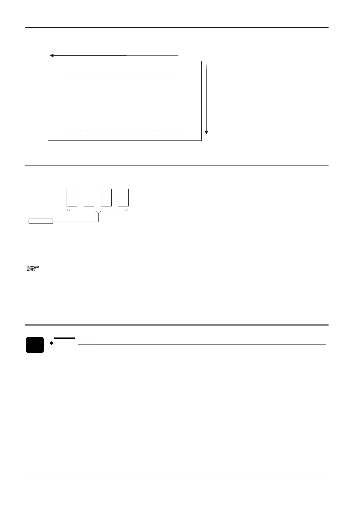
Example Configuration of external input relay (X)
XF, XE, XD, XC, XB, XA, X9, X8, X7, X6, X5, X4, X3, X2, X1, X0
X1F, , X10
, X20
, X5100
, X5110
X2F,
X510F,
X511F,
................
................
1.2.4 Timer Contacts (T) and Counter Contacts (C)
Addresses of timer contacts (T) and counter contacts (C) correspond to the TM and CT instruction numbers and
depend on the PLC type.
0, 1, 2 ...
T0, T1 .......................... T2999
C3000, C3001 ............. C3072
Decimal
e.g. for FP2:
Since addresses for timer contacts (T) and counter contacts (C)
correspond to the TM and CT instruction numbers, if the TM and CT
instruction sharing is changed by system register 5, timer and counter
contact sharing is also changed.
1.2.5 Error alarm relays
NOTE
Error alarm relays are only available for FP2SH/FP10SH.
Restrictions of error alarm relays (see page 36)
Erro
r alarm relays a
re designed to facilitate the analysis of error conditions and to record errors. Therefore in the
special data registers a buffer has been defined so that the user has access to information about errors and
their occurrence, including the actual number of error relays in the TRUE state, the order they were set to TRUE
and the time at which the first error relay was set to TRUE.
When an error relay is set to TRUE by the error alarm program because the corresponding error situation has
arisen, the number of error relays in the TRUE state stored in special data register DT90400 increases by one
each time an error occurs. Relay numbers will be stored in DT90401 through DT90419 in the order that they
were set to TRUE. If at least one of the error alarm relays E0 through E2047 is set to TRUE, R9040
(sys_bIsErrorAlarmRelayOn) will be set to TRUE. The time at which the first error alarm relay was set to TRUE
is stored in DT90420 through DT90422.

 Loading...


