Basics
33
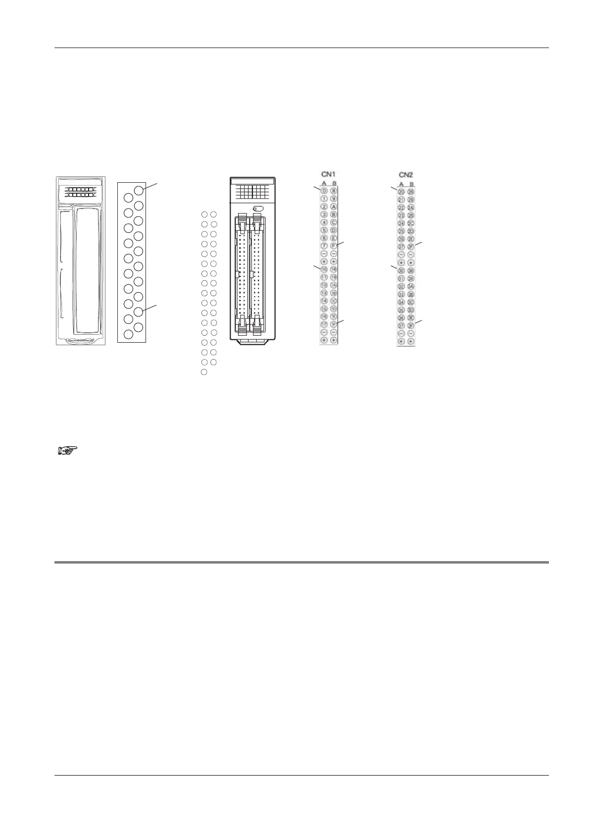
number begins at zero for the outputs.
In-/Output addresses are numbered serially. Supposing the first slot of your PLC contains an input module with
16 inputs and the second slot of your PLC contains an output module with 32 outputs, the input module
occupies the addresses: %IX0.0 - %IX0.15, the output module: %QX1.0 - %QX2.15. The physical address
depends therefore on the module type (I/Q), the slot number (word address) the module is assigned and the
relay number (bit address).
%QX1.0
%QX3.15
%QX2.0
%QX2.15
%QX3.0
%QX4.15
%QX4.0
%QX1.15
%IX0.0
%IX0.15
4
2
0
COM
COM
NLC
NLC
6
D
B
9
F
5
3
1
7
C
A
8
E
3
6
5
4
7
-
+
-
+
12
11
10
13
16
15
14
17
B
E
D
C
F
-
+
-
+
1A
19
18
1B
1E
1D
1C
1F
Output moduleInput module
This shows how the hexadecimal counting of 0-F for 0-15 is converted. The address assignment can be found
in your hardware description.
Find the tables with all memory areas in your hardware description.
When using timers, counters, set/elapsed values, and data registers,
the bit address does not have to be indicated.
You can also enter the register number (R9000, DT9001/90001) or the
FP address, e.g. “X0” (input 0), instead of the IEC address.
1.2.3 Specifying Relay Addresses
External input relay (X), external output relay (Y), internal relay (R), link relay (L) and pulse relay (P)The lowest
digit for these relay’s adresses is expressed in hexadecimals and the second and higher digits are expressed in
decimals as shown below.

 Loading...


