Appendix Programming Information
1255
40.7 Relays and memory areas
40.7.1 Relays and memory areas for FP0
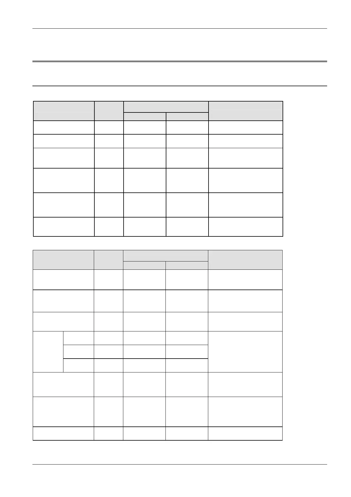
Relays [bits]
Available address area Type Memory
size
F/P IEC
Function
External input relays 208 X0–X12F %IX0.0–
%IX12.15
Turn on or off based on external
input.
External output relays 208 Y0–Y12F %QX0.0–
%QX12.15
Turn on or off external outputs
based on the operation result.
Internal relays
1)
1008 R0–R62F %MX0.0.0–
%MX0.62.15
Used internally by the PLC
program to store bit information.
Timer relays
1)
2)
144 T0–T99/
C100–C143
%MX1.0–
%MX1.99/
%MX2.100–
%MX2.143
Turn on when the value set with
a TM instruction for the timer with
the same number has reached 0.
Counter relays
1)
2)
144 C100–C143/
T0–T99
%MX2.100–
%MX2.143/
%MX1.0–
%MX1.99
Turn on when the value set with
a CT instruction for the counter
with the same number has
reached 0.
Special internal relays 64 R9000–R903F %MX0.900.0–
%MX0.903.15
Turn on or off based on specific
conditions. Used internally as a
flag.
Memory area [words]
Available address area Type Memory
size
F/P IEC
Function
External input relays 13 WX0–WX12 %IW0–
%IW12
Code for specifying 16 external
input points as one word (16 bits)
of data.
External output relays 13 WY0–WY12 %QW0–
%QW12
Code for specifying 16 external
output points as one word (16
bits) of data.
Internal relays
1)
63 WR0–WR62 %MW0.0–
%MW0.62
Code for specifying 16 internal
relays as one word (16 bits) of
data.
C10/C14/C
16
1660 DT0–DT1659 %MW5.0–
%MW5.1659
C32/SL1 6144 DT0–DT6143 %MW5.0–
%MW5.6143
Data
registers
1)
T32C 16384 DT0–DT16383 %MW5.0–
%MW5.16383
Data memory used in a program.
Data is handled in 16-bit units
(one word).
Timer/counter set value
area
1)
2)
144 SV0–SV143 %MW3.0–
%MW3.143
Data memory for storing the set
values of timers or counters. The
values are stored by
timer/counter number.
Timer/counter elapsed
value area
1)
2)
144 EV0–EV143 %MW4.0–
%MW4.143
Data memory for storing the
elapsed values during operation
of timers or counters. The values
are stored by timer/counter
number.
Special data registers 112 DT90000–
DT90111
%MW5.90000–
%MW5.90111
Data memory for storing settings
and error codes.

 Loading...


