Edge detection instructions
886
Part III FP Instructions
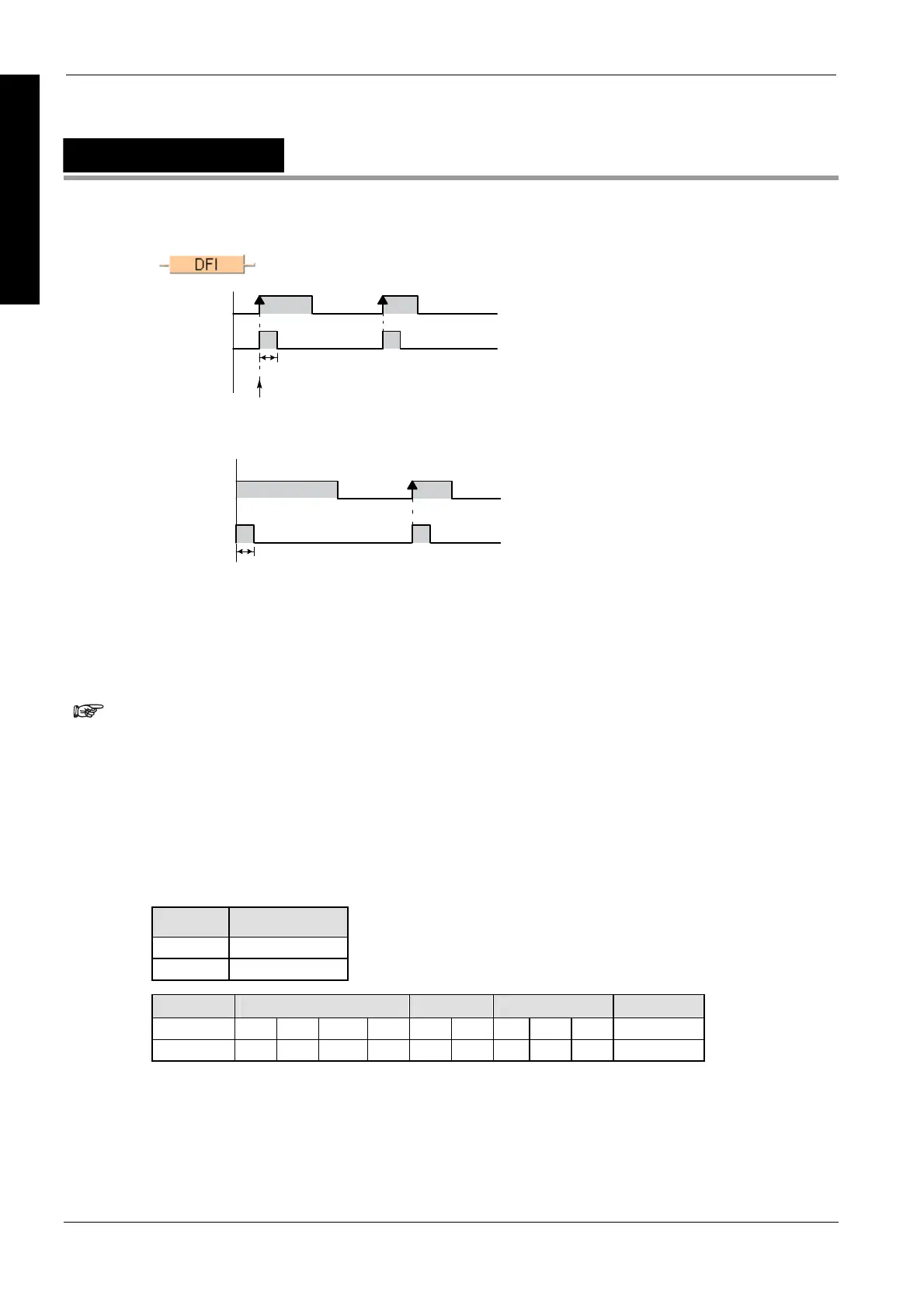
DFI
Rising edge differential (initial execution type)
Input signal
Ouput signal
Leading edge
One scan
Detection of the input signal’s rising edge is also assured at the first scan.
Input signal
Output signal
One scan
You may use an unlimited number of DFI functions.
If the input signal = TRUE already when the system is turned on and this signal should not be
interpreted as the first rising edge, the DF function must be used instead.
PLC types
Availability of DFI (see page 1319)
Be careful when programming with commands that effect the order in which a
program is carried out, e.g. jump or loop instructions within a sequential
function chart or a function block. The order of the instructions might change
depending on the time when the instruction is carried out or the input value.
Specific basic JUMP and LOOP instructions are:
- MC (see page 1007) to MCE (see page 1008)
- JP (see page 1009) to LBL (see page 1013)
- F19_SJP (see page 1010) to LBL (see page 1013)
- LOOP (see page 1012) to LBL (see page 1013)
Variable Data type
input BOOL
output BOOL
For Relay T/C Register Constant
i X Y R L T C - - - -
o - Y R L - - - - - -
Description
When a rising edge of the input signal (input i) is detected, this function changes the status of the
output signal (output o) to TRUE for the duration of the scan.
Data types
Operands

 Loading...


