EasyManuals Logo

Panasonic FP Series User Manual

Panasonic FP Series
1345 pages
To Next Page IconTo Next Page
To Previous Page IconTo Previous Page
Page #1127 background imageLoading...
Page #1127 background image
Analog unit instructions
1126
Part IV Tool Instructions
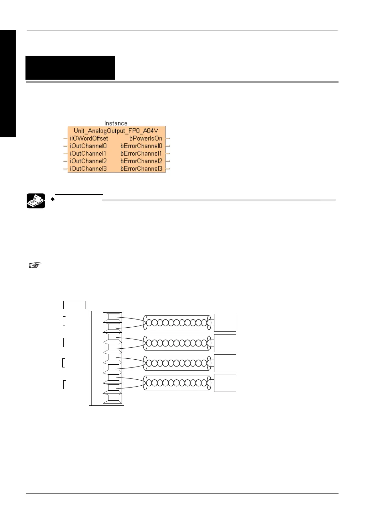
Unit_AnalogOutput
_FP0_A04V
Reads data from the FP0-A04 unit
REFERENCE
For technical information, please refer to the manual FP0 Analog unit manual on your FPWIN Pro
installation CD.
PLC types see on page 1333
The function block needs two PLC cycle scans to write all four channels into the
FP0-A04V Unit. Do not use pulse relay at EN input.
Wiring of analog outputs
V0
COM
V1
COM
V2
COM
V3
COM
NC
A
A
A
A
OUTPUT
A: Analog device
Description
This function block reads digital data from the FP0-A04 unit voltage output type from the output
channels 0–3 and stores the analog data in the input channels iOutChannel0–iOutChannel3. The
valid range is from -10–+10 V (-2000–+2000).

Table of Contents

Other manuals for Panasonic FP Series

Questions and Answers:

Question and Answer IconNeed help?

Do you have a question about the Panasonic FP Series and is the answer not in the manual?

Panasonic FP Series Specifications

General IconGeneral
MountingDIN rail
TypePLC
Communication InterfaceRS-232, RS-485, Ethernet (depending on model)
Input Voltage100-240V AC or 24V DC (depending on model)
Output TypeRelay, Transistor
I/O PointsVaries by model
Operating Temperature0°C to 55°C
DimensionsVaries by model
WeightVaries by model

Related product manuals