Data transfer via communication ports
756
Part III FP Instructions
F161_MRCV
Read serial data from the MCU's COM port
This instruction also exists as a P instruction (for FP2/2SH, FP3/5, FP10/10SH PLC types), which
is only executed at the rising edge of the EN trigger. Select [Insert P instruction] from the
"Instructions" pane if you require a P instruction. To facilitate reuse, the instruction then appears
under "Recently used" in the pop-up menu. Press <Ctrl>+<Shift>+<v> within the programming
area to open the list of recently used elements.
Do not execute F161_MRCV unless the end of reception has been verified by evaluating the
"reception done" flag. Polling the data using F161_MRCV does not work correctly! The "reception
done" flag can be evaluated using the IsReceptionDone (see page 760) function. Or use the
system vari
able sys_bIsComPort1
ReceptionDone, sys_bIsComPort2ReceptionDone, or
sys_bIsToolPortReceptionDone, depending on the port. The end of reception can also be
determined by time-out using the IsReceptionDoneByTimeOut (see page 761) function or by
che
cking the conte
nts of the receive buffer.
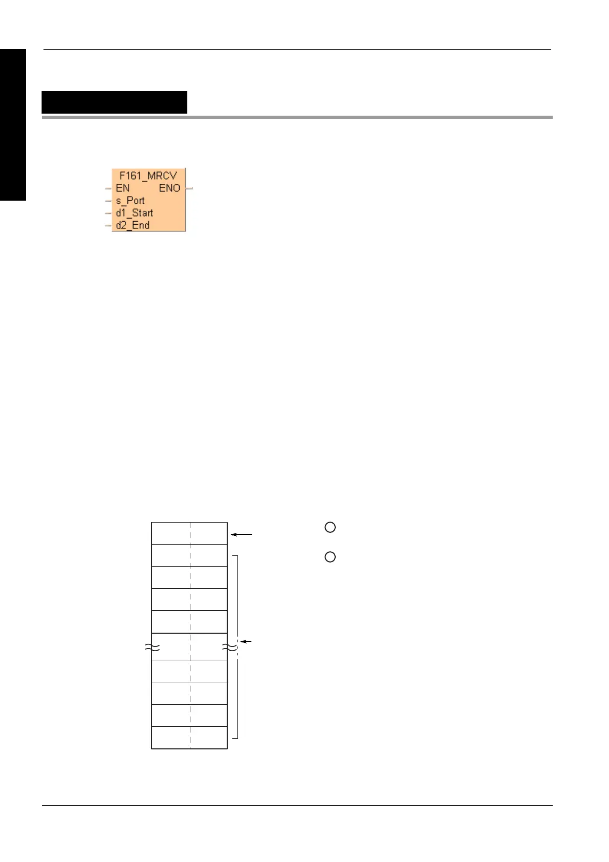
The number of bytes received is stored in the initial address specified by d1_Start of the receive
buffer. If the data received exceeds the ending address specified by b2_End, an operation error is
detected. The data which has been received up to d2_End will be stored. F161_MRCV also clears
the receive buffer (see page 746), resets the "reception done flag" and allo
ws further receptio
n of
data.
F161_MRCV is supported by all PLCs: If suitable functions and system variables are used instead
of flags, PLC-independent programs can be created which handle communication for CPU
communication ports as well as for MCU ports. PLCs not using MCU ports simply do not translate
the F161_MRCV instruction.
1
Storage area for the number
of bytes received
d1_start
d1_start + 1
d1_start + 2
d1_start + 3
d1_start + 4
d2_end
d2_end - 1
d2_end - 2
d2_end - 3
2
Storage area for the data
received
Description
Use this instruction to copy the data received in the MCU from the external device to the specified
receive buffer in the CPU. The receive buffer is defined by d1_Start and d2_End.
Receive
buffer

 Loading...


