Bit-shift instructions
556
Part III FP Instructions
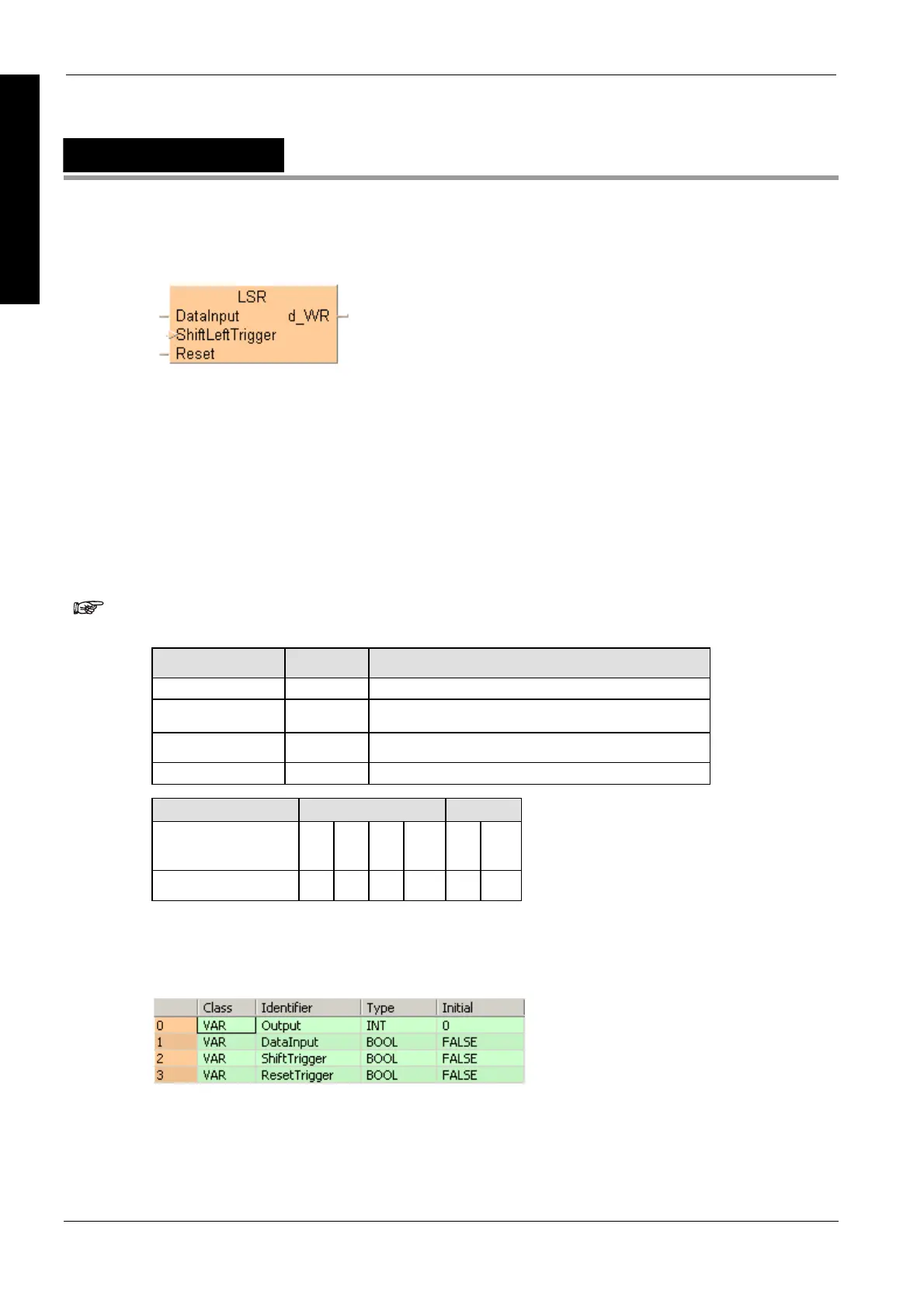
LSR
Left shift register
DataInput: specifies the state of new shift-in data:
new shift-in data 1: when the input is ON
new shift-in data 0: when the input is OFF
ShiftLeftTrigger: shifts 1 bit to the left when the leading edge of the trigger is detected
Reset: turns all the bits of the data area to 0 if the trigger is in the ON-state
The area available for this instruction is only the word internal relay (WR).
PLC types Availability of LSR (see page 1328)
Word internal relay (WR) number range, depends on the free area in the Extras
Options Compile Options Address Ranges menu.
Variable Data type Function
DataInput BOOL when ON, shift-in data = 1, when OFF, shift-in data = 0
ShiftLeftTrigger BOOL shifts one bit to the left when ON
Reset BOOL resets data area to 0 when ON
d_WR ANY16 specified data area where data shift takes place
For Relay T/C
DataInput,
ShiftLeftTrigger,
Reset
X Y R L T C
d_WR - - WR - - -
Description
Shifts 1 bit of the specified data area (d_WR) to the left (to the higher bit position). When
programming the LSR instruction, be sure to program the data input (DataInput), shift
(ShiftLeftTrigger) and reset triggers (Reset).
Data types
Operands
Example
In this example the function has been programmed in ladder diagram (LD) and structured text (ST).
POU header
All input and output variables used for programming this function have been declared in the POU
header.

 Loading...


