Pulse output instructions
1209
Part IV Tool Instructions
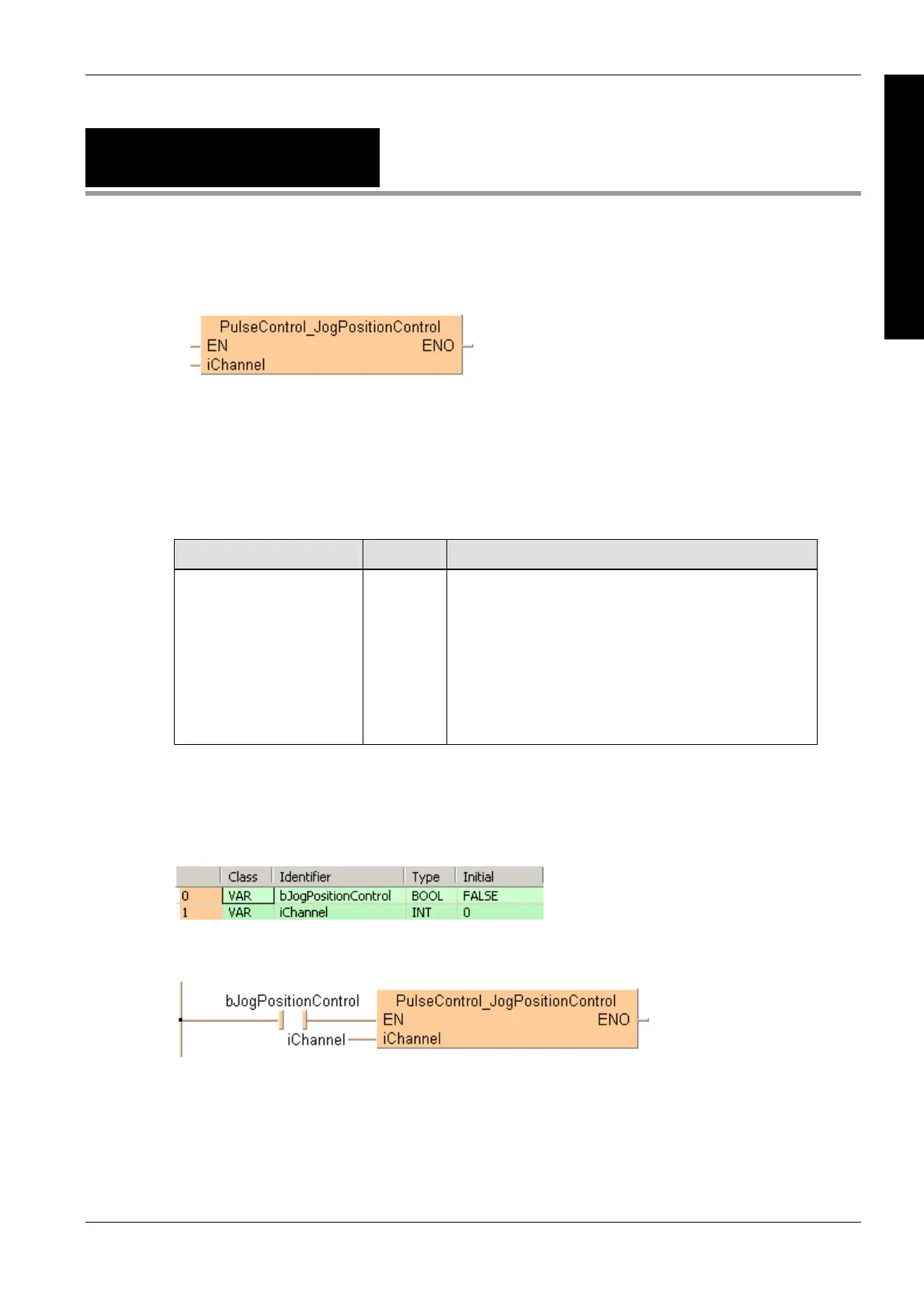
PulseControl_JogPosition
Control
Starts position control
See also:
Pulse output tool instructions in the online help
FP instructions F171_PulseOutput_Jog_Positioning (see page 1055)
PLC types see page 1329
Variable Data type Function
iChannel INT Pulse output channel:
FP
: 0, 2
FP-X R: 0, 1
FP-X 16K C14T: 0, 1, 2
FP-X 32K C30T, C60T: 0, 1, 2, 3
FP0R: 0, 1, 2, 3
FP0: 0, 1
FP-e: 0, 1
Description
This instruction sets and resets bit 6 of the pulse output control code (see page 1021) to start
position control on the channel specified by iChannel. The position control trigger is used with the
JOG operation instructions PulseOutput_Jog_Positioning0_FB (see page 1181) and
Pulse
Output_J
og_Positioning1_FB (see page 1184).
Data types
Example
In this example the function has been programmed in ladder diagram (LD) and structured text (ST).
The same POU header is used for all programming languages.
POU header
All input and output variables used for programming this function have been declared in the POU
header.
Body
LD
ST
When programming with structured text, enter the following:
if (bJogPositionControl) then
PulseControl_JogPositionControl(iChannel := iChannel);
end_if;

 Loading...


