System register instructions
994
Part III FP Instructions
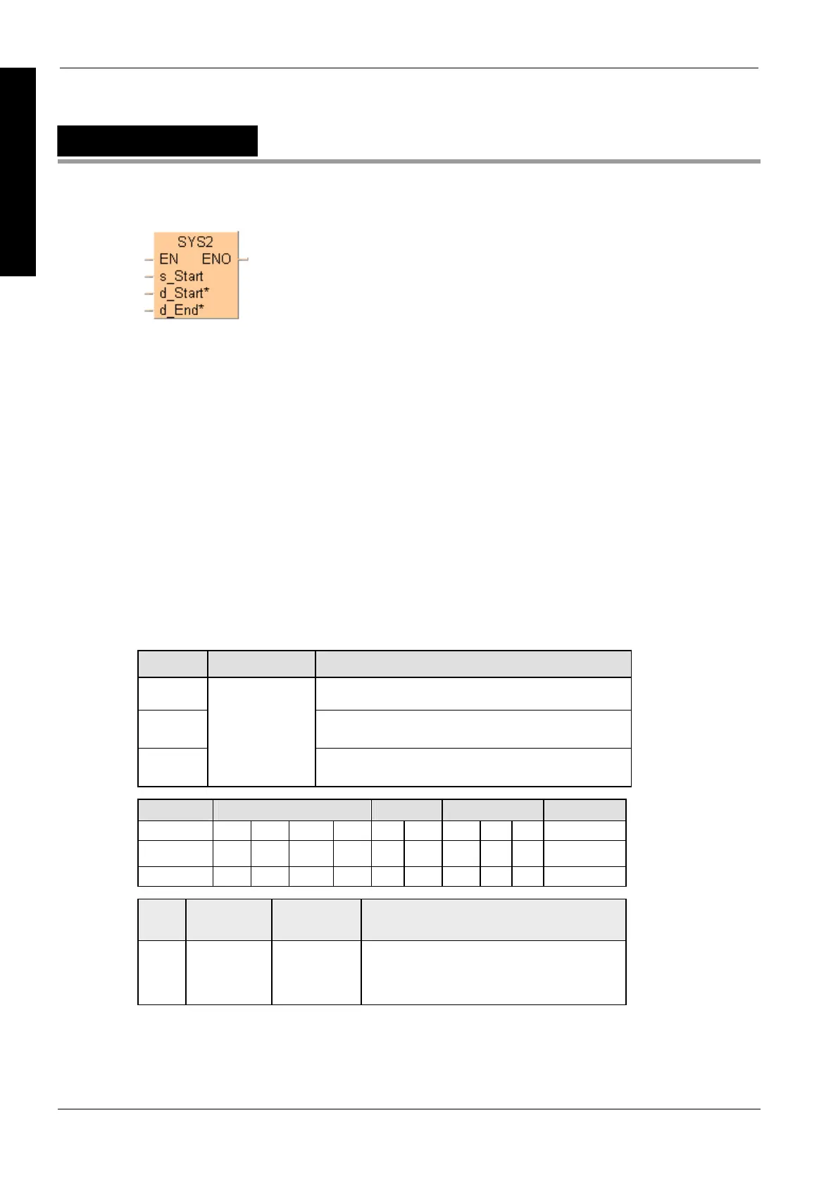
SYS2
Change System Register Settings for PC Link Area
You can change the values in system registers 40 - 47 (with the FP0R, FP- 32k, FP-X also 50 -
57), PC link area.
To add an enable input and enable output to the instruction, select [With EN/ENO] from the
"Instructions" pane (LD, FBD or IL editor). To reuse an instruction select "Recently used" from the
context menu or press <Ctrl>+<Shift>+<v> in the programming window.
Precautions during programming
Executing this instruction does not rewrite the contents of the system ROM in the
control unit. As a result, turning the power supply off and then on again rewrites
the contents of the system registers specified by the tool software.
A value between 40 and 47 should be specified for d_Start* or d_End*. Also, the
values should always be specified in such a way that d_Start* d_End*.
The values of the system registers change, so a verification error may occur
when the program is verified.
PLC types
Availability of SYS2 (see page 1331)
Variable Data type Function
s_Start Contains new values for the system registers defined by
remaining two variables.
d_Start* First system register (between 40-47) to receive new value.
Must be a constant
d_End*
ANY16
Last system register (between 40-47) to receive new value.
Must be a constant
For Relay T/C Register Constant
s_Start - - - - - - DT - - -
d_Start* - - - - - - - - - dec. or hex.
d_End* - - - - - - - - - dec. or hex.
No. IEC
address
Set If
R9007
R9008
%MX0.900.7
%MX0.900.8
permanently
for an instant
d1 > d2
the specified value is outside the ranges
specified for the various system registers
setting values
Description
While the PLC is in RUN mode, SYS2 changes the settings for the specified system registers.
s_Start contains the new values for those system registers defined between d_Start* and d_End*.
Data types
Operands
Error flags

 Loading...


