Data transfer via communication ports
754
Part III FP Instructions
ClearReceiveBuffer
Reset the receive buffer
The "reception done" flag turns to FALSE.
PLC types see see page 1318
Variable Data type Function
Port
ANY16
Communication port
Must be a constant
FP-X, FP and FP2, FP2SH (V1.4 or later):
PLC communication ports:
Value: SYS_COM1_PORT or SYS_COM2_PORT or
SYS_TOOL_PORT
MCU communication port:
Value: 16#xx01 (COM1), 16#xx02 (COM2)
xx = slot number (hexadecimal) of the MCU (e.g. 16#0001:
COM1 in slot 0, 16#0A02: COM2 in slot 10, 16#1401: COM1
in slot 20)
Other PLCs:
The command will be compiled to F144_TRNS, which works
on the COM port of the CPU (the parameter d_Port will be
ignored)
For Relay T/C Register Constant
Port WX WY WR WL SV EV DT LD FL dec. or hex.
No. IEC address Set If
R900B %MX0.900.11 for an instant
R9009 %MX0.900.9 for an instant
the communication port specified by Port
does not exist.
Description
This instruction resets the receive buffer to be ready for the next data at the port number Port.
Data types
Operands
Error flags
Example
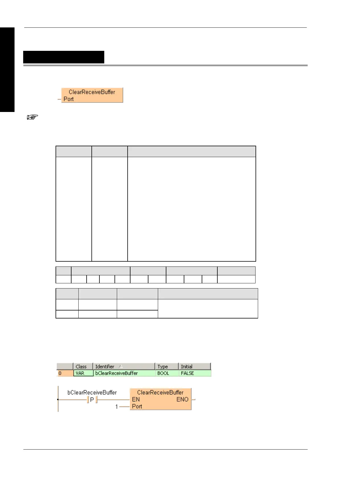
In this example the function has been programmed in ladder diagram (LD) and structured text
(ST).The same POU header is used for all programming languages.
POU header
All input and output variables used for programming this function have been declared in the POU
header.
LD

 Loading...


