Process control instructions
967
Part III FP Instructions
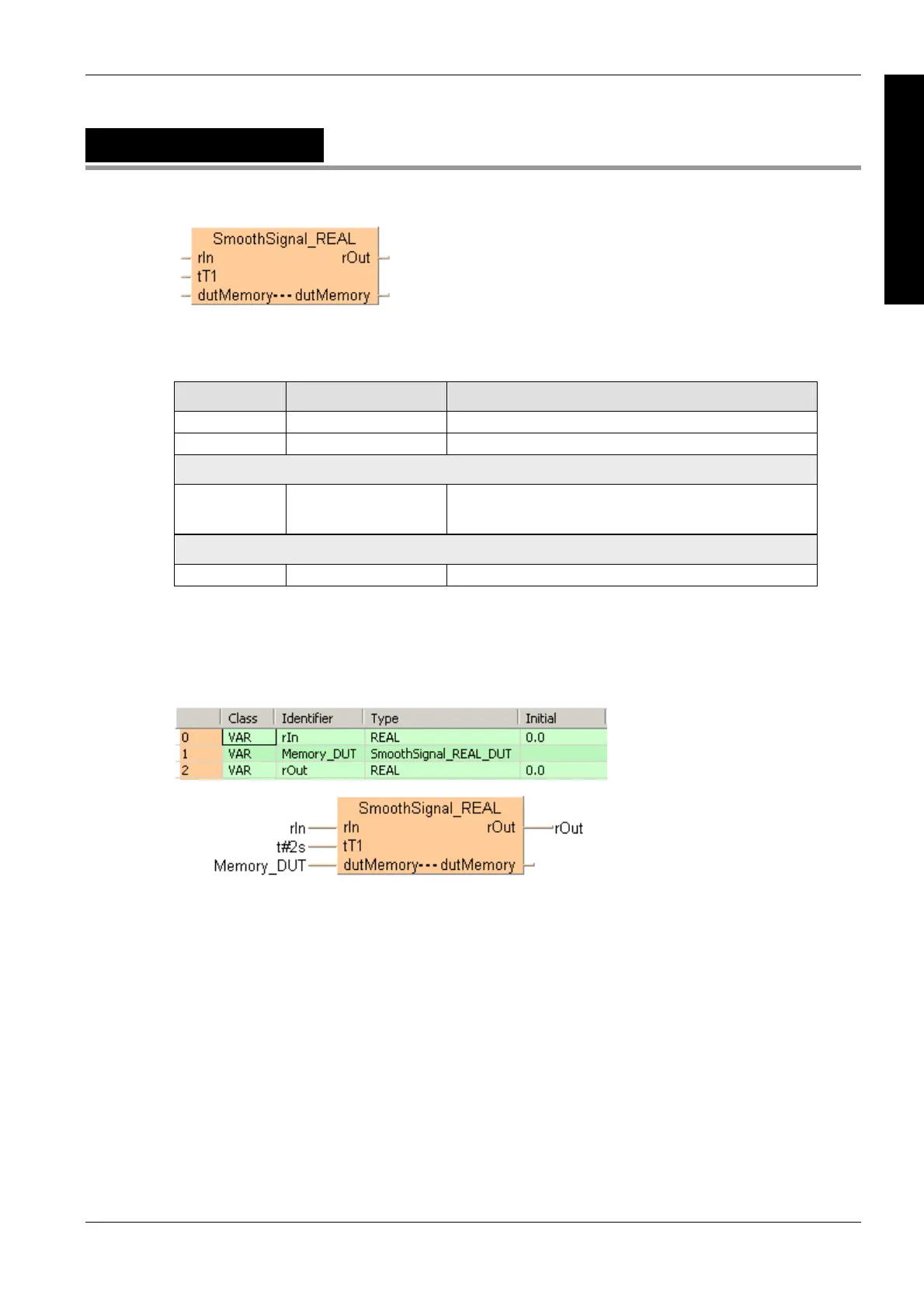
SmoothSignal_REAL
Smooth REAL signals
PLC types see page 1331
Input variable Data type Function
rIn REAL Input signal
tT1 TIME Time constant of the 1st order low-pass filter
Input/output variable
dutMemory dutMemory Instance-dependent data memory structure, which serves as the
internal memory of the function. As with the instance name of a
function block, it may be neither initialized nor written in the body!
Output variable
rOut REAL Output signal
Description
This instructions uses a 1st order delay time tT1 to smooth the REAL input value at iIN.
Data types
Example
In this example the function has been programmed in ladder diagram (LD) and structured text (ST).
The same POU header is used for all programming languages.
POU header
All input and output variables used for programming this function have been declared in the POU
header.
LD
ST
When programming with structured text, enter the following:
SmoothSignal_REAL(rIn := rIn,
tT1 := t#2s,
dutMemory := Memory_DUT,
rOut => rOut);

 Loading...


