FP-e display instructions
970
Part III FP Instructions
F180_SCR
Screen display instruction
PLC types
Availability of F180_SCR (see page 1335)
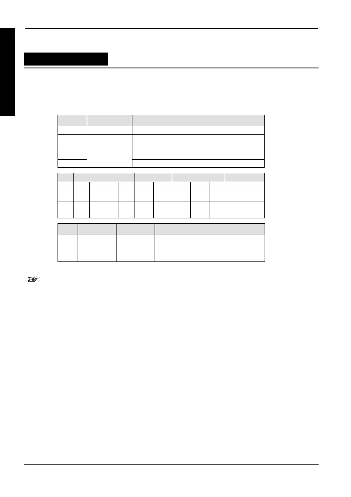
Variable Data type Function
s1 ANY16 Specifies "s1" registration screen
s2 ARRAY [0..2] OF
INT, WORD
Specifies the head of the screen display control data (3
words).
s3 Specifies the data displayed in the upper section.
s4
ANY16
Specifies the data displayed in the lower section.
For Relay T/C Register Constant
s1 WX WY WR - SV EV DT IX IY dec. or hex.
s2 WX WY WR - SV EV DT IX IY
s3 WX WY WR - SV EV DT - -
s4 - WY WR - SV EV DT IX IY -
No. IEC address Set If
R9007
R9008
%MX0.900.7
%MX0.900.8
permanently
for an instant
the area specified using the Index modifier
exceeds the limit.
the value for "s1" or "s2" is outside of the
range specified.
Special register "DT9***" cannot be specified for the lower section
display data "s4."
This instruction cannot be used in an interrupt program.
Detailed information, please refer to the online help:
Examples of control register
ASCII code and its display
7-segment data and its display
Description
This instruction sets up the screen display in the normal mode (N) and switch mode (S) of the FP-e
unit.
Data types
Operands
Error flags

 Loading...


