FP-e display instructions
975
Part III FP Instructions
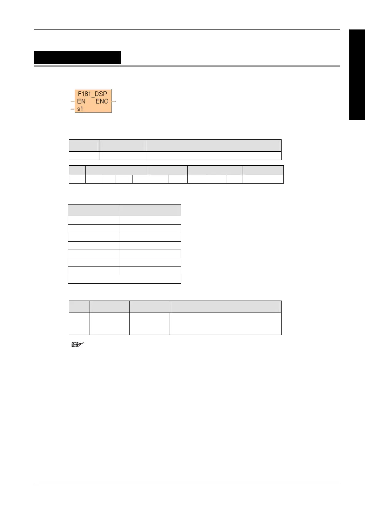
F181_DSP
Screen change instruction
PLC types
Availability of F181_DSP (see page 1322)
Variable Data type Function
s1 ANY16 Display mode and No. (0 to 7 can be specified).
For Relay T/C Register Constant
s1 WX WY WR - SV EV DT IX IY dec. or hex.
Specifying "s1" registration display
Values for "s1" Display type
0 N mode 1st screen
1 N mode 2nd screen
2 S mode 1 st screen
3 S mode 2nd screen
4 R mode 1st screen
5 R mode 2nd screen
6 I mode 1st screen
7 I mode 2nd screen
(N=normal mode, S=switch mode, R=register mode, I=I/O monitor mode).
No. IEC address Set If
R9007
R9008
%MX0.900.7
%MX0.900.8
permanently
for an instant
the area specified using the Index modifier
exceeds the limit.
the value "s1" is not "0" to "7".
If a value other than "0" to "7" is specified for "s1", an operation
error will occur.
This instruction cannot be used during an interrupt program.
Description
The FP-e display mode is changed to the one specified using s1.
Data types
Operands
Error flags
Example
In this example the function has been programmed in ladder diagram (LD) and structured text
(ST).The same POU header is used for all programming languages.