Pulse output instructions
1021
Part III FP Instructions
35.2 Writing the pulse output control code
The special data register where the high-speed counter and pulse output control code are stored
can be accessed with the system variable sys_wHscOrPulseControlCode. (The system variable
sys_wHscOrPulseControlCode corresponds to special data register DT90052.)
Operations performed by the pulse output control code
Setting/resetting near home input
Continuing/stopping pulse output (forced stop)
Enabling/disabling counting operations
Resetting the elapsed value (software reset) of the high-speed counter
Clearing high-speed counter and position control instructions (FP0R only)
The control code settings for each channel can be monitored using the system variables
sys_wHscChannelxControlCode or sys_wPulseChannelxControlCode (where x=channel number).
The settings of this system variable remain unchanged until another setting operation is executed.
Performing a forced stop may cause the elapsed value at the PLC
output side to differ from the elapsed value at the motor input side.
Therefore, you must execute a home return after pulse output has
stopped.
Setting the near home input is not possible if counting is prohibited or
if a software reset is performed.
Description for FP:
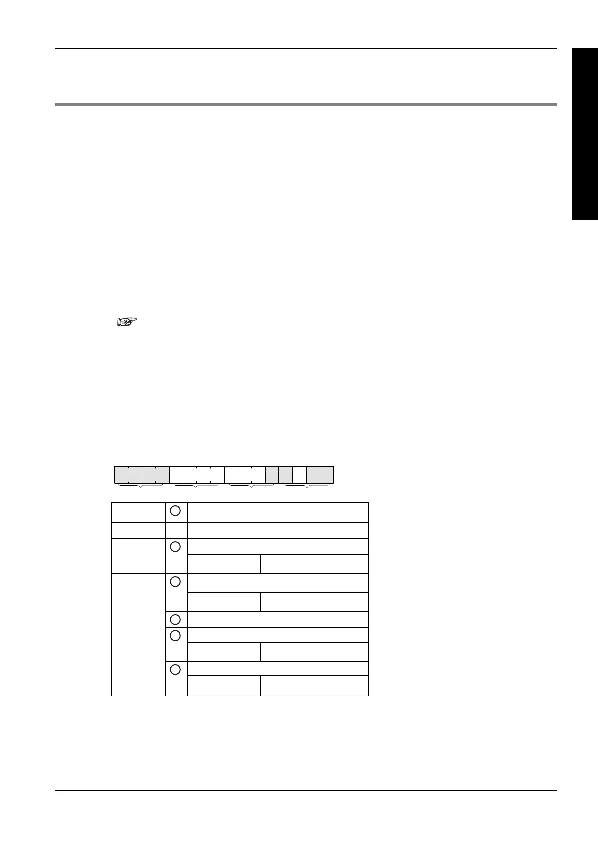
Bits 0–15 of the control code are allocated in groups of four. The bit setting in each group is
represented by a hex number (e.g. 0002 0000 0000 1001 = 16#2009).
15 12 11 8 7 4 3 0
IIIIIIIV
Group IV
1
Channel number (channel n: 16#n)
Group III
0 (fixed)
Near home input (bit 4)
Group II
2
0: FALSE 1: TRUE
Pulse output (bit 3)
3
0: continue 1: stop
4
0 (bit 2, fixed)
Count (bit 1)
5
0: permit 1: prohibit
Reset elapsed value to 0 (bit 0)
Group I
6
0: no 1: yes

 Loading...


