Appendix Programming Information
1259
1)
The number of points noted above is the number reserved as the calculation memory. The actual number of
points available for use is determined by the hardware configuration.
2)
There are hold and non-hold type memory areas. When the power supply turns off or the mode is changed
from RUN to PROG mode, hold type areas are stored and non-hold type areas are reset.
C10/C14/C16/C32:
The hold type and non-hold type areas are fixed. For information on the size of each area, refer to the
performance specifications.
T32/F32:
The settings of the hold type areas and non-hold type areas can be changed using the system registers.
T32:
If the battery is empty and additional hold areas have been defined, the hold/non-hold operation becomes
unstable. The data value will become indefinite. It is cleared to 0 the next time the power is turned on. See.
3)
The number of points for timer and counter relays can be changed using system register 5. The numbers in
the table are the default settings.
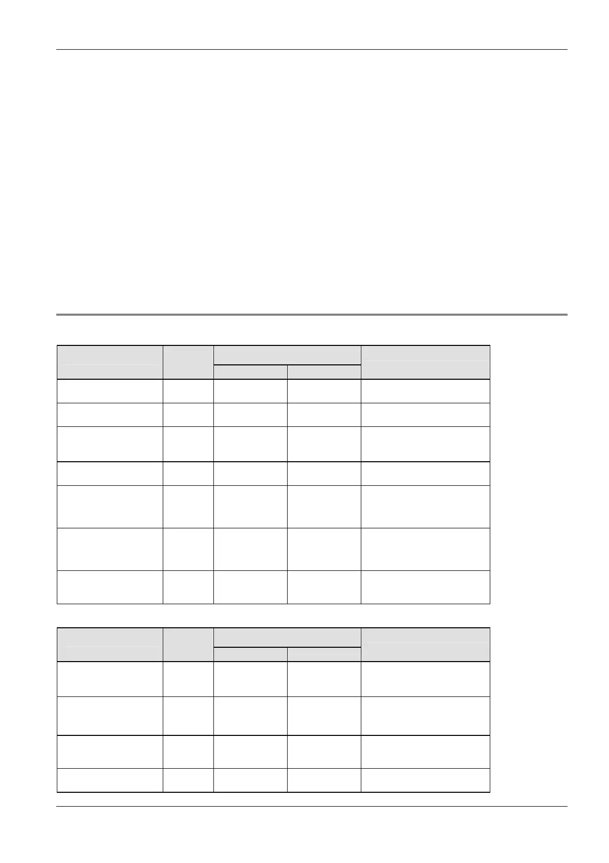
40.7.3 Relays and memory areas for FP-Sigma
Relays [bits]
Available address area Type Memory
size
FP IEC
Function
External input relays
1)
1184 X0–X73F %IX0.0–
%IX73.15
Turn on or off based on external
input.
External output relays
1)
1184 Y0–Y73F %QX0.0–
%QX73.15
Turn on or off external outputs
based on the operation result.
Internal relays
2)
4096 R0–R255F %MX0.0–
%MX0.255.15
Used internally by the PLC
program to store bit information.
Link relays
2)
2048 L0–L127F %MX7.0.0–
%MX7.63.15
Shared by multiple PLCs
connected using PLC link.
Timer relays
2)
3)
1024 T0–T1007/
C1008–C1023
%MX1.0–
%MX1.1007/
%MX2.1008–
%MX2.1023
Turn on when the value set with
a TM instruction for the timer with
the same number has reached 0.
Counter relays
2)
3)
1024 C1008–C1023/
T0–T1007
%MX2.1008–
%MX2.1023/
%MX1.0–
%MX1.1007
Turn on when the value set with
a CT instruction for the counter
with the same number has
reached 0.
Special internal relays 176 R9000–R910F %MX0.900.0–
%MX0.910.15
Turn on or off based on specific
conditions. Used internally as a
flag.
Memory area [words]
Available address area Type Memory
size
FP IEC
Function
External input relays
1)
74 WX0–WX73 %IW0–
%IW73
Code for specifying 16 external
input points as one word (16 bits)
of data.
External output relays
1)
74 WY0–WY73 %QW0–
%QW73
Code for specifying 16 external
output points as one word (16
bits) of data.
Internal relays
2)
256 WR0–WR255 %MW0.0–
%MW0.255
Code for specifying 16 internal
relays as one word (16 bits) of
data.
Link relays 128 WL0–WL127 %MW7.0–
%MW7.127
Code for specifying 16 link relays
as one word (16 bits) of data.

 Loading...


