Program execution control instructions
1017
Part III FP Instructions
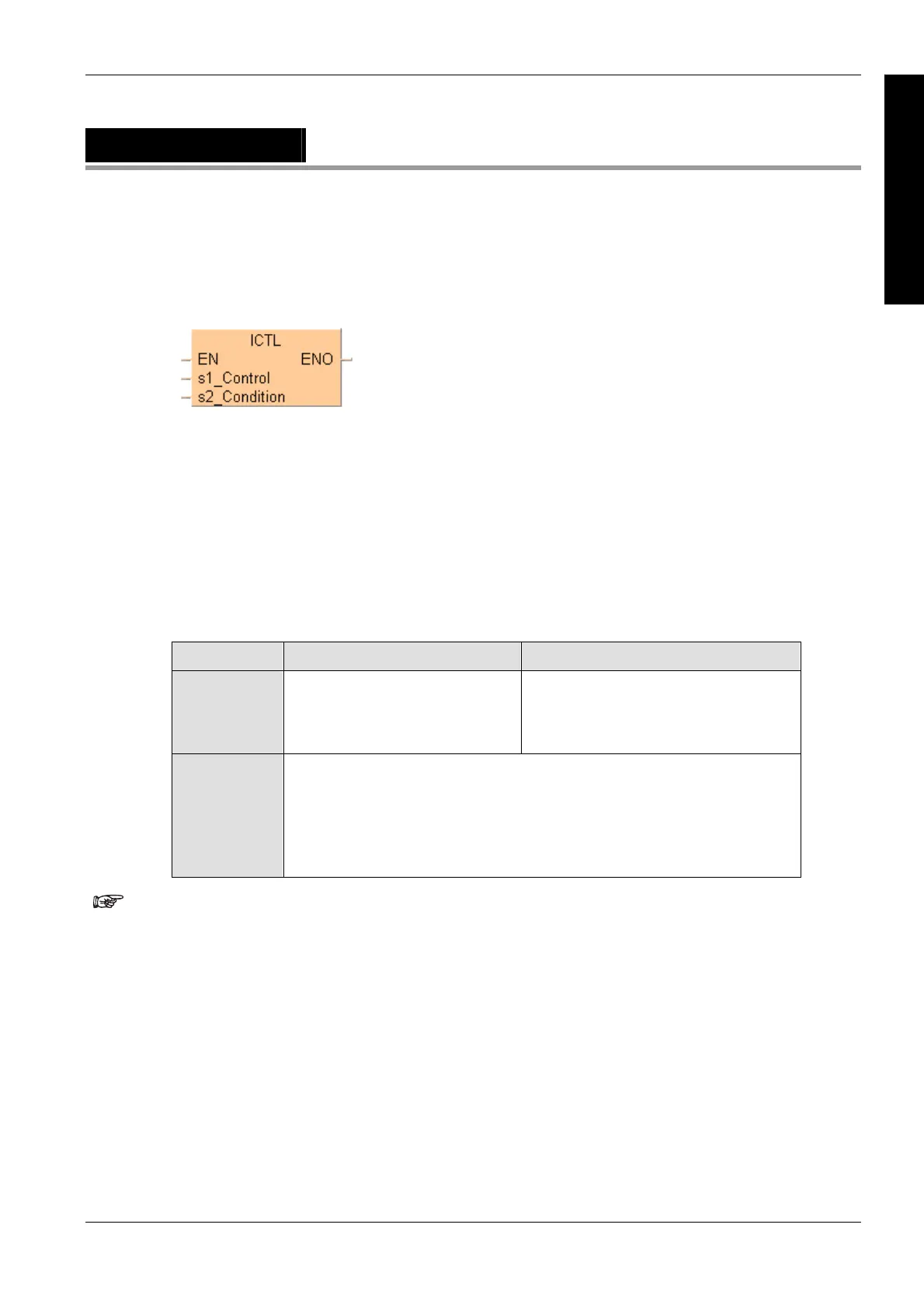
ICTL
Interrupt Control
s1_Control 16-bit equivalent constant or 16-bit area for interrupt control setting
s2_Condition 16-bit equivalent constant or 16-bit area for interrupt trigger
condition setting
The number of interrupt programs available is:
16 interrupt module initiated interrupt programs (INT 0–INT 15)
8 advanced module (special modules, like positioning,...) initiated interrupt
programs (INT 16–INT 23)
1 periodic interrupt program (INT 24) (Time base 0.5ms selectable for FP2/2SH,
FP10SH)
Be sure to use ICTL instructions so that they are executed once at the rising edge of the ICTL
trigger using the DF instruction.
Two or more ICTL instructions can have the same trigger.
Bit 15 .. 8 7 .. 0
s1_Control
16#
Selection of control function
00: Interrupt "enable/disable" control
01: Interrupt trigger reset control
Interrupt type selection
00: Interrupt module (INT 0–15)
01: Advanced module (INT 16–23)
02: Periodic interrupt (INT 24)
s2_Condition
2#
Bit 0: 0 Interrupt program 0 disabled
Bit 0: 1 Interrupt program 0 enabled
Bit 1: 0 Interrupt program 1 disabled
...
Bit 15: 1 Interrupt program 15 enabled
Example: s2 = 2#0000000000001010
The current enable/disable status of each interrupt module initiated
interrupt can be checked by monitoring the special data register
(see page 1254) DT90025.
The curr
ent enable/disable status of e
ach non-interrupt module
initiated interrupt can be checked by monitoring the special data
register DT90026.
The current interrupt interval of the periodic interrupt can be
checked by monitoring the special data register DT90027.
If a program is written into an interrupt task, the interrupt concerned
will be enabled automatically during the initialization routine when
starting the program.
With the ICTL instruction an interrupt task can be enabled or
disabled by the program.
Description
The ICTL instruction sets all interrupts to enable or disable. Each time the ICTL instruction is
executed, it is possible to set parameters like the type and validity of interrupt programs. Settings
can be specified by s1_Control and s2_Condition.

 Loading...


