Pulse output instructions
1192
Part IV Tool Instructions
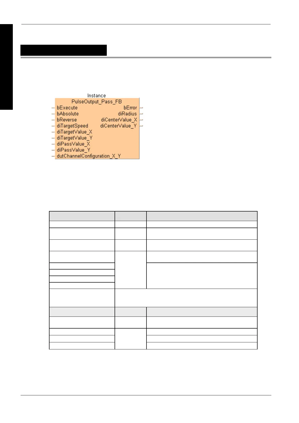
PulseOutput_Pass_FB
Circular interpolation (pass position)
This non-inline instruction is part of the tool instructions for pulse output. For a detailed description
of the instruction(s) used internally, please refer to the online help: F176_PulseOutput_Pass (see
page 1081). Use PulseInfo_IsActive (see page 1223
) to check if the control flag for the selected
channel is FALSE.
PLC types see page 1330
Input variable Data type Function
bExecute BOOL Activates the function block
bAbsolute
Absolute value control = TRUE, Relative value control =
FALSE
bCounterclockwise
Operation connection mode: Reverse = TRUE, Forward =
FALSE
diTargetSpeed Target speed: Composite speed of both axes = 100–20000
(100Hz–20kHz)
diTargetValue_X
diTargetValue_Y
diPassValue_X
diPassValue_Y
DINT
Target value [pulses]: -8388608–8388607
dutChannelConfiguration_X_Y Predefined system DUT for channel configuration:
PulseOutput_Channel_Configuration_DUT
Channel: 0, 2
Output variable Data type Function
bError BOOL Refers to an internal mismatch of input values to avoid a
PLC error.
diRadius Radius [pulses]
diCenterValue_X X-axis center value [pulses] = -8388608–8388607
diCenterValue_Y
DINT
Y-axis center value [pulses] = -8388608–8388607
Description
Pulses are output from two channels in accordance with the parameters in the function block and in
the specified DUT, so that the path to the target position forms an arc. Pulses are output from the
specified channel when the control flag for this channel is FALSE and the execution condition is
TRUE.
Data types

 Loading...


