Timer instructions
926
Part III FP Instructions
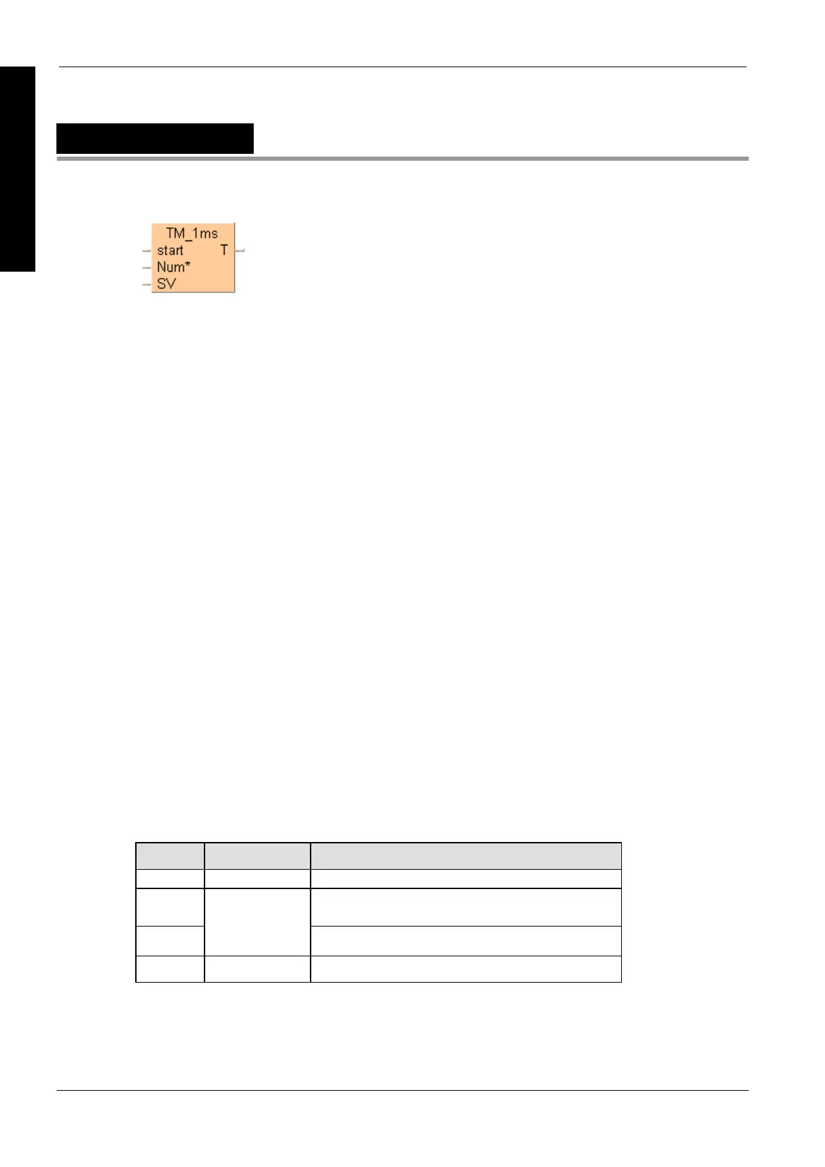
TM_1ms
Timer for 1ms intervals (0 to 32.767s)
Instead of using this FP instruction, we recommend using the related IEC instruction
tmTM_1ms_FB (see page 913).
Please refer also to Advantages of the IEC instructio
ns in the online help.
The areas used for the instruction are:
Preset (Set) value area: SV
Count (Elapsed) value area: EV
When the mode is set to RUN mode, the Preset (Set) value is transferred to the SV. If the trigger of
the timer instruction start is in the ON-state, the Preset (Set) value is transferred to the EV from the
SV.
During the timing operation, the time is subtracted from the EV.
The scan time is also subtracted from the EV in the next scan.
The timer contact T turns ON, when the EV becomes 0.
Calculation of the timing operation:
timing operation = time set value - 0 to 1/2 of units (0.5ms) + scan time
Example:
150ms time set value and 8ms PLC scan time
Upper limit = 150 - 0 + 8 = 158ms
Lower limit = 150 -0.5 +8 = 157.5ms
The result is a timing operation from 157.5ms to 158ms.
PLC types
Availability of TM_1ms (see page 1332)
Variable Data type Function
start BOOL starts timer
Num* timer contact
Must be a constant
SV
ANY16
timer address in system registers 5 and 6
T BOOL set value
Description
The TM_1ms instruction sets the ON-delay timer for 0.001s units (0 to 32.767s).
Data types

 Loading...


