Pulse output instructions
1185
Part IV Tool Instructions
PulseOutput_Jog_
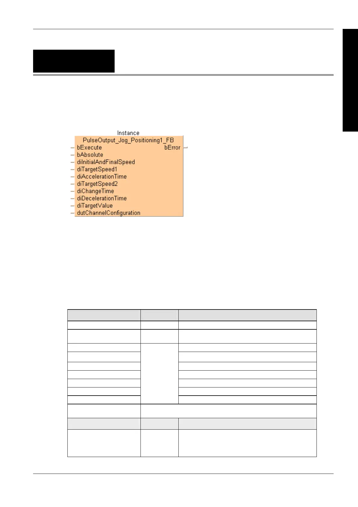
Positioning1_FB
JOG operation and positioning
The target speed can be changed once when the position control trigger input turns to TRUE.
This non-inline instruction is part of the tool instructions for pulse output. For a detailed description
of the instruction(s) used internally, please refer to the online help:
F171_PulseOutput_Jog_Positioning (see page 1055)
Use PulseInfo_IsActive (see page 1223)
to check if the control flag for the selected channel is
FALSE.
Use PulseControl_PulseO
utputStop (see page 1213) to stop pulse output on a specified channel.
Use PulseControl_D
eceleratedStop (see page 1202) to perform a decelerated stop.
PLC types see see page 1329
Input variable Data type Function
bExecute BOOL With edge or permanent if change of speed required
bAbsolute BOOL:=FALSE Only incremental mode supported, must be FALSE always,
otherwise an error is output.
diInitialAndFinalSpeed Initial and final speed = 1 to 50000 (1Hz–50kHz)
diTargetSpeed1 Target speed = 1 to 50000 (1Hz–50kHz)
diAccelerationTime Acceleration time = 1ms–32760ms
diTargetSpeed2 Target speed = 1 to 50000 (1Hz–50kHz)
diChangeTime Change time = 1ms–32760ms
diDecelerationTime Deceleration time = 1ms–32760ms
diTargetValue
DINT
Target value [pulses]: -2147483648–2147483647
dutChannelConfiguration Predefined system DUT for channel configuration:
PulseOutput_Channel_Configuration_DUT
Output variable Data type Function
bError BOOL Refers to an internal mismatch of input values to avoid a PLC
error.
TRUE if the applied channel is not enabled in the system
registers or if bAbsolute is TRUE
Description
This instruction is used for JOG operation. The specified number of pulses is output after the
position control trigger input has turned to TRUE. A deceleration is performed before the target
value is reached and pulse output stops. Pulses are output from the specified channel when the
control flag for this channel is FALSE and the execution condition is TRUE.
Data types

 Loading...


